


Chapter 3: Installation 25 of 60
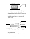
Machine Mount
The GH Hopper must be machine mounted. There are a few items to review before
placement and mounting of the rate monitor system begins.
First, verify the machine flange dimensions match the cast spool-mounting flange.
Verify that the machine throat is physically capable of supporting the rate monitoring system
with a full load of material and vacuum loading equipment installed.
Verify all clearances on the top and beside the processing machine. This is to insure that all
motors, hoppers, control panels, etc. have adequate room for proper operation and servicing.
Refer to the assembly drawing with the unit for actual height and width dimensions.
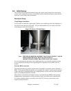
Using proper lifting equipment, lift the rate monitor. Affix the rate monitor to the processing
machine.
Take care to insure proper orientation with adequate access to operator controls, mix
chamber, and metering units.
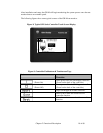
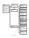
3-3 Electrical Connections
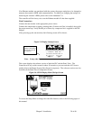
The standard rate monitor system is designed to operate on 120/1/60 supply voltage. For
exact current requirements, check the GH Hopper serial number tag, located on the right side
of the PLC enclosure.
If a step down transformer was provided, it should never be used to power anything other
than the rate monitor. Loading equipment, etc. must be powered by another power source. As
well as possibly overloading the transformer, the additional equipment may induce power line
noise that may affect the operation of the rate monitor
The transformer will be mounted and wired by the customer or your installer. If company or
local codes require fusing or disconnects, these items must be supplied, wired, and mounted
by the customer.
Ensure that the power entrance location on the rate monitor panel remains unchanged. Make
sure that the proper size wire and proper wire routing techniques are used when installing the
Note: While in operation, the GH system applies horizontal and vertical
pressures to the mounting flange. If there is a question as to the
mechanical stability of a mounting flange, contact the manufacturer’s
engineering department.
Note: Allow at least 36” clearance around the GH System to provide adequate
room for cleaning, servicing, etc.
Note: Larger rate monitors may need to be braced as part of the installation.
Note: Never weld on the GH Hopper, support stand, machine or mezzanine
without first removing the control panel and verifying that the hopper is
properly grounded.
Note: Each GH System MUST be connected to a separate source of power. Do
not connect other electrical equipment, especially self-contained hopper
loaders, on the same line as the rate monitor.