


v
Table of Contents
CHAPTER 1: SAFETY................................................................ 7
1-1 How to Use This Manual .............................................................................................7
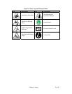
Safety Symbols Used in this Manual.....................................................................7
1-2 Warnings and Precautions ..........................................................................................9
1-3 Responsibility ............................................................................................................10
General Responsibility ........................................................................................10
Operator Responsibility .......................................................................................10
Maintenance Responsibility.................................................................................12
Reporting a Safety Defect ...................................................................................12
CHAPTER 2: FUNCTIONAL DESCRIPTION ........................... 13
2-1 Models Covered in This Manual................................................................................13
2-2 General Description................................................................................................... 13
Accessories .........................................................................................................13
Customer Service................................................................................................14
2-3 Typical Features and Components ........................................................................... 15
Mechanical Features ...........................................................................................15
Controller Features..............................................................................................15
System Component Description..........................................................................16
Extruder Inductive Proximity Switch ..................................................................16
Surge Hopper .......................................................................................................16
Weigh Hopper...................................................................................................... 17
Operator Control Panel Display (optional on GH-M units, 1 required per facility
for setup and Maintenance).................................................................................. 17
2-4 Optional Components................................................................................................ 22
Ethernet Module ..................................................................................................22
Pneumatic Slide Gate below surge hopper .........................................................23
Low Level Proximity Sensors ..............................................................................23
2-5 Safety Features .........................................................................................................23
CHAPTER 3: INSTALLATION.................................................. 24
3-1 Uncrating the Equipment...........................................................................................24
3-2 Mechanical Installation ..............................................................................................24
Site Requirements...............................................................................................24
Mounting Configurations .....................................................................................24
Machine Mount....................................................................................................25
3-3 Electrical Connections............................................................................................... 25
3-4 Pneumatic Connections ............................................................................................ 26
3-5 Initial Set-up .............................................................................................................. 27
Mechanical Set-up...............................................................................................27
Weigh Hopper Installation................................................................................... 27
Extruder RPM connection ...................................................................................27
Final Connections ................................................................................................28
Controller Set-up .................................................................................................29
GH Controller Menu Structure ............................................................................ 30
GH Calibration.....................................................................................................30