


Chapter 3: Installation 27 of 60
3-5 Initial Set-up
This section will discuss the mechanical setup and control system setup of the rate monitor
system. After reading this section, you should be familiar with the mechanical setup and the
electronic control setup of the rate monitor.
Mechanical Set-up
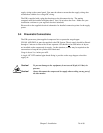
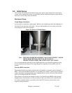
Weigh Hopper Installation
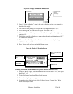
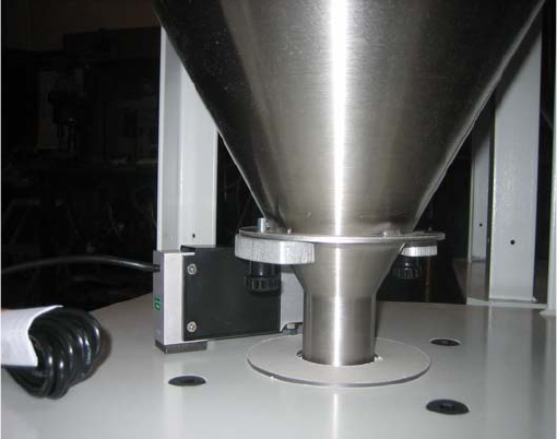
It is necessary to install the weigh hopper. Remove the weigh hopper from the shipping box
and install it onto the load cell bracket. Two provided thumbscrews are used to secure the
weigh hopper to the load cell bracket.
Figure 12: Picture of Weigh Hopper
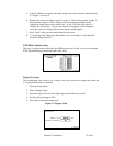
It is very important the tube stub of the weigh hopper does not touch the supplied dust ring.
It is also important the flange of the weigh hopper be completely flush with the load cell
bracket.
Extruder RPM connection
The supplied inductive proximity switch must be mounted to accurately read the Extruder’s
RPM. If the optional Ethernet module was purchased, the extruder’s speed may be reported
to the controller via communications (see communications section at the end of this manual,
NOT AVAILABLE FOR GH-F UNITS).
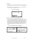
The proximity switch must be mounted securely, and read the actual RPM of the extruder.
Supplementary documentation on this proximity switch is provided from its manufacturer.
To wire the supplied inductive proximity switch the PLC enclosure, please refer to the
supplied wiring schematics.
Note: THE WEIGH HOPPER ASSEMBLY MUST HANG FREELY AND BE
FREE FROM FRICTION, WITH NO MECHANICAL
OBSTRUCTIONS OTHER THAN THE LOAD CELL ITSELF.