


Chapter 5: Advanced Motherboard Setup
5-3
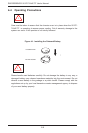
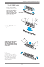
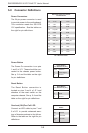
Figure 5-1. Control Panel Header Pins
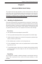
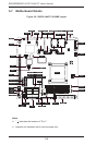
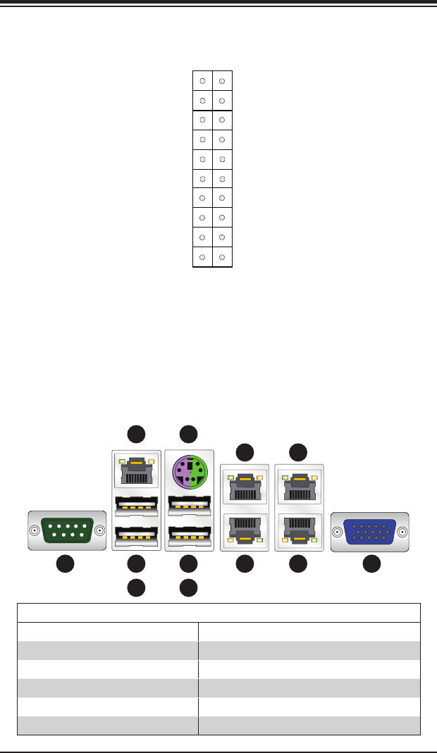
5-3 Rear I/O Ports
The I/O ports are color coded in conformance with the PC 99 specication. See
Figure 5-2 below for the colors and locations of the various I/O ports.
Figure 5-2. Rear I/O Ports
Rear I/O Ports
1 COM Port 1 7 PS/2 Keyboard/Mouse
2 USB Port 5 8 Gb LAN Port 2
3 USB Port 4 9 Gb LAN Port 1
4 Dedicated IPMI LAN Port 10 Gb LAN Port 4 (X9SPV-LN4F only)
5 USB Port 9 11 Gb LAN Port 3 (X9SPV-LN4F only)
6 USB Port 8 12 VGA Port
Power Button
OH/Fan Fail LED
1
NIC1 LED
Reset Button
2
HDD LED
Power LED
Vcc
Vcc
Vcc
Vcc
Ground
Ground
19 20
X
Ground
NMI
X
Vcc
NIC2 LED
X
X
1
2 5
4
3
7
8
9
10
11
12
6