Chapter 5: Advanced Motherboard Setup
5-13
DOM Power Connector
A power connector for SATA DOM
(Disk On Module) devices is located at
JSD1. Connect an appropriate cable
here to provide power support for your
DOM devices.
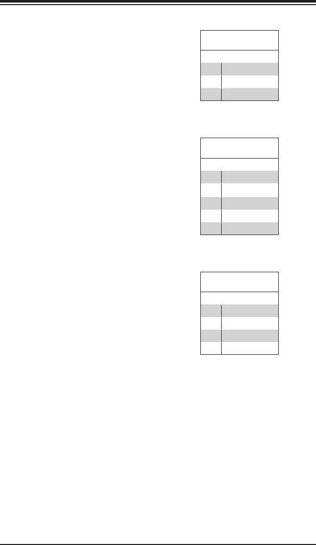
DOM PWR
Pin Denitions
Pin# Denition
1 +5V
2 Ground
3 Ground
Power Supply SMBus I
2
C Header
The power System Management Bus
header at JPI
2
C2 is used to monitor
the status of the power supply, fan and
system temperature. See the table on
the right for pin denitions.
PWR SMB
Pin Denitions
Pin# Denition
1 Clock
2 Data
3 PWR Fail
4 Ground
5 +3.3V
IPMB
A System Management Bus header for
IPMI 2.0 is located at IPMB. Connect
the appropriate cable here to use the
IPMB I
2
C connection on your system.
IPMB Header
Pin Denitions
Pin# Denition
1 Data
2 Ground
3 Clock
4 No Connection


