


SLEU063
10 TVP5160EVM User’s Guide
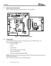
5 Hardware Setup
The following describes how to set up the hardware for the TVP5160EVM.
1. Connect the TVP5160EVM boards together using the 120-pin board connector on
each board.
2. Connect a CVBS input to the TVP5160 board and a component cable to the YPbPr
outputs of the ADV7311 board.
NOTE: For evaluation it is recommended that the YPbPr component video outputs be
used in order to bypass the internal video decoder of the TV or video display.
3. Connect the parallel port cable from the TVP5160EVM to the PC.
NOTE: There are footprints for a dc jack and a DB25 connector on the ADV7311 board,
but the default power and I
2
C is provided by the TVP5160 board via the 120-pin
connector, P2.
4. Connect the 5-V power supply to the dc jack on the TVP5160 board. A green LED on
each board should now be lit.