


SLEU063
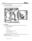
12 TVP5160EVM User’s Guide
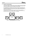
7 WinVCC4 Quick Start
The following describes the steps to take within WinVCC4 in order to get video out of the
TVP5160EVM.
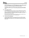
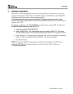
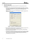
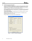
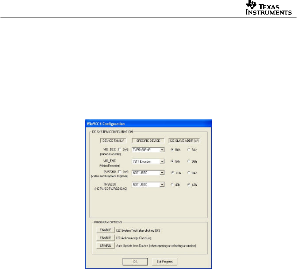
1. Once WinVCC4 is executed, the WinVCC4 Configuration screen appears. This dialog
box is used to configure the I
2
C bus. Next to VID_DEC, select the TVP5160 and ensure
the I
2
C address is set to 0xB8. This should match the I2C ADDR jumper on the
TVP5160 board.
NOTE: If WinVCC4 is running and the TVP5160 board I
2
C address is changed, power
must be cycled on the EVM.
Figure 3. WinVCC4 – I
2
C Configuration Screen
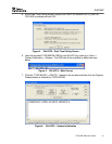
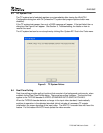
2. Next to VID_ENC, select the ADV7311 and ensure the I
2
C address is set to 0x54. This
should match the I2C ADDR jumper on the ADV7311 board.
3. Ensure that all other boxes are selected as Not Used and that all “Program Options”
buttons are set to Enabled. Click OK.
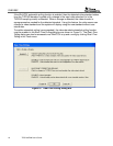
4. If there are no I
2
C communication issues, then the Real-Time Polling window will display
next. If there are I
2
C issues, an I2C Test Report box will display. Completely exit out of
WinVCC4, double check the parallel port cable connections, cycle power on the
TVP5160EVM and re-run WinVCC4.