


29
Operations
CONTENTS
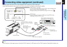
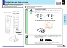
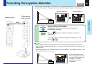
Projection on the screen (continued)
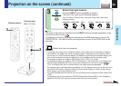
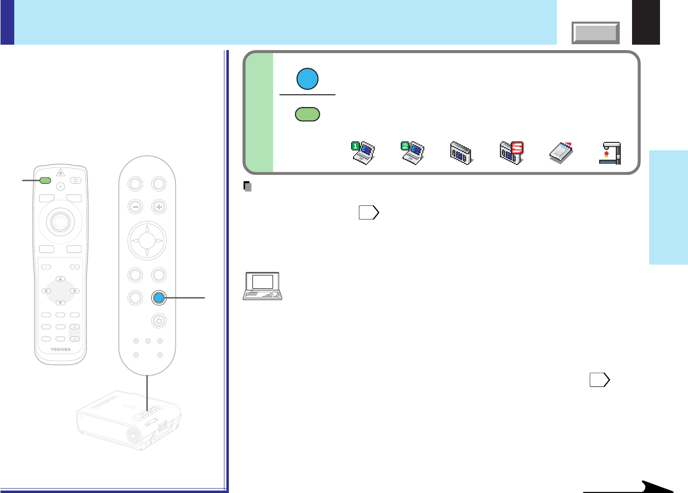
Select the input source.
Press the INPUT button repeatedly to select it.
The icon of the input source selected appears.
(You can select “Camera” when using the model with a document
imaging camera.)
3
Continued
MENU
ON/STANDBYINPUT
L-CLICK R-CLICK
ENTER
KEYSTONE
AUTO
SET
EXIT
PIP
FREEZE
MUTECALL
RESIZE
VOLUME/ADJUST
3
LASER
TEMP LAMP ON
BUSY FAN
KEYSTONE
SET
AUTOAUTO
EXIT
ENTER
MENU
INPUT
VOL/ADJ.
3
TEMP
LAMPON
BUSY FAN
ON/STANDBY
KEYSTONE
SET
AUTOAUTO
EXIT
ENTER
MENU
INPUT
VOL/ADJ.
ON/STANDBY
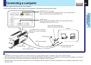
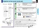
(Signal sent from the computer)
• If you project an image from a computer with an LCD screen while monitoring the image on
the computer, the image may not be projected properly, depending on the computer model.
In this case, turn off the computer display. For details on controlling the computer display, etc.,
refer to the computer’s manual and description on the software for the computer used.
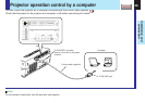
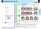
• The projector projects an image by XGA signal (1024 x 768) in full screen.
• The projector projects an image by VGA or SVGA signal in full screen size, the image quality
may be slightly degraded. But, when you set the “Screen size” in the menu screen
54
to
“Thru”, the display size will be reduced without the image quality be degraded.
• The projector has simplified display compatibility with the signals whose picture dots are more
than that of XGA signal. (However, letters and lines can be inequal or a part can be missing.
Some signals may not be projected at all.)
• It is recommended to set an external monitor connected to the computer to XGA mode (1024
x 768).
• The projector can be also applied to DDC2B (Display Data Channel 2B). If your computer is
applied to the DDC, start up your computer after turning on the projector.
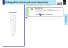
Note
The types of input sources selected when the INPUT button is pressed repeatedly can be
set from the menu screen.
48
(At shipping from factory, the projector is set so that the RGB signal source input to the
COMPUTER IN 1 connector and the video signal source input to the VIDEO jack can be
selected.)
INPUT
INPUT
Remote control
Control panel
(Main unit side)
COMPUTER-1 COMPUTER-2
Video S-video Memory card Camera