


Controls and Functions
Vidikron Vision 85 Owner’s Operating Manual 7
PRE
L
IMINAR
Y
2.2
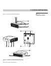
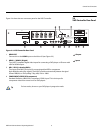
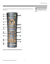
Vision 85 Rear Panel
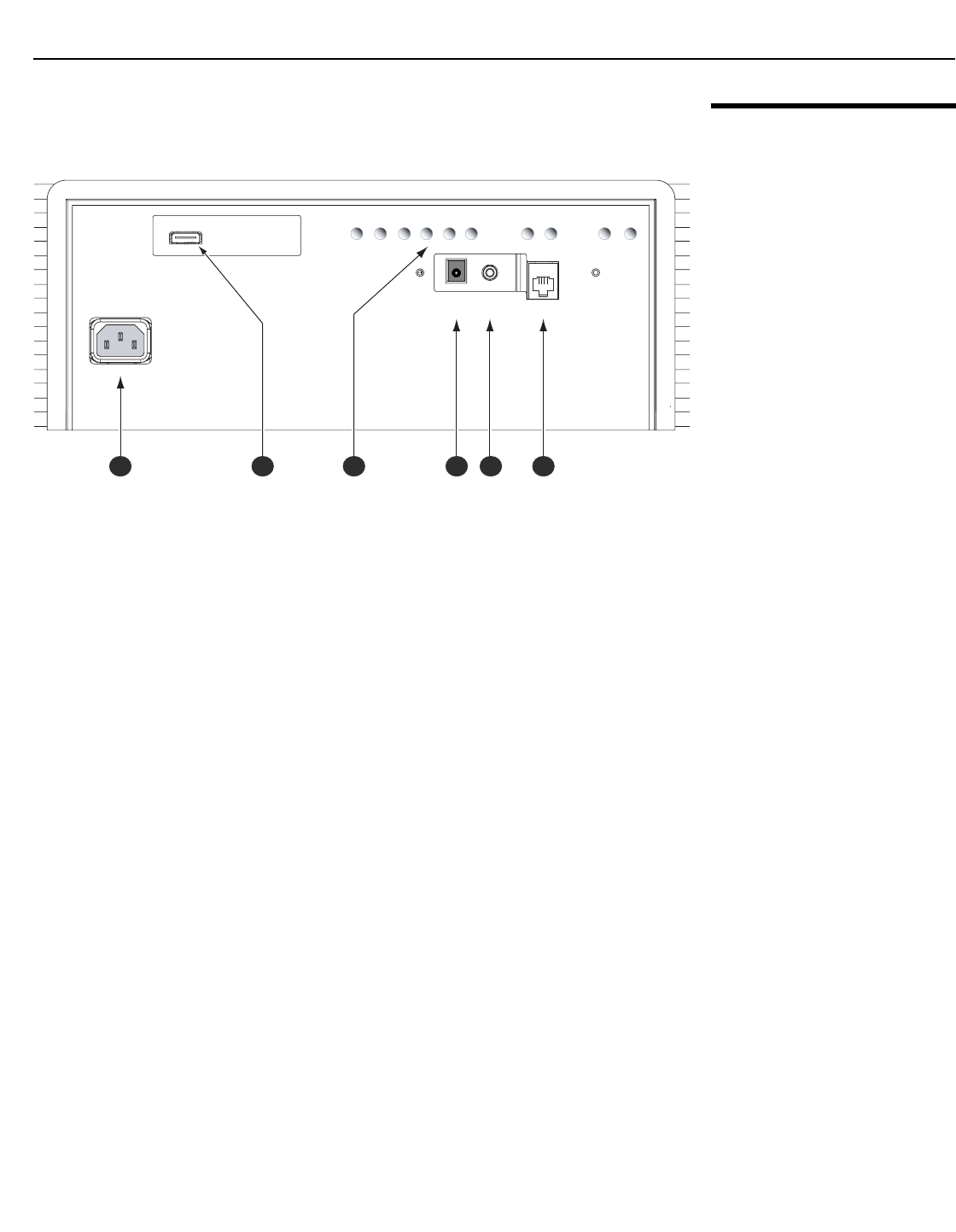
Figure 2-2 shows the Vision 85 rear panel.
Figure 2-2. Vision 85 Rear Panel
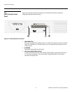
1. POWER INPUT (100 to 240 VAC)
Connect the Vision 85 to power here.
2. HDMI INPUT
An HDCP-compliant, digital video input for connecting the HDMI output from the VHD
Controller.
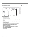
3. BUILT-IN KEYPAD
Used to navigate the Vision 85 on-screen menus. Refer to Vision 85 Built-In Keypad on
page 14 for more information.
4. 12-VOLT (200 mA) TRIGGER OUTPUT (cylindrical, DC power supply-type jack)
Connection for a retractable screen, screen masking or other, 12-volt trigger-activated
equipment. Outputs +12 volts/200 mA when the projector is turned on.
5. WIRED IR (3.5-mm, mini phono jack)
Not used. To use an external infrared receiver or wired remote control with this
projector, connect it to the IR input on the VHD Controller (see
Figure 2-4).
6. RS-232C INPUT (RJ-11 female connector)
Connect the RS-232 output from the VHD Controller here, using the provided
communication cable.
HDMI
HDMI
AC IN 100-240V 50-60Hz
AC IN 100-240V 50-60Hz
TRIGGER
TRIGGER
IR
IR
RS-232 OUT
RS-232 OUT
RETURN ENTER DOWN UP LEFT RIGHT
RETURNENTERDOWNUPLEFTRIGHT
ON
ON
MENU
MENU
ASPECT
RATIO
ASPECT
RATIO
STANDBY
STANDBY
1 2 3 4 5 6