


Controls and Functions
Vision Model 140/150 Installation/Operation Manual 7
PRE
L
IMINAR
Y
2.2
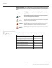
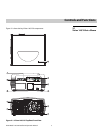
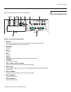
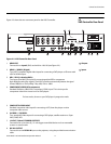
Vision 140/150 Input Panel
Figure 2-2 shows the Vision 140/150 rear input panel.
Figure 2-2. Vision 140/150 Input Panel
1. RS232 IN
Connect the RS-232 output from the VHD Controller here, using the provided
RJ11-to-DB9 adapter and communication cable.
2. RS232 OUT
Not used.
3. RS422
Not used.
4. GPIO
Not used.
5. REMOTE
Wired input from an external remote control or infrared receiver.
6. ETHERNET
Reserved for future use.
7. INPUT 3 (Video) / INPUT 4 (S-Video)
Not used. Connect all video sources to the VHD Controller.
8. INPUT 2 (DVI)
HDCP-compliant digital video input. Connect the HDMI output from the VHD Controller
to this input.
9. INPUT 1 (RGBHV)
Not used. Connect all video sources to the VHD Controller.
10. INPUT 5 (Option 1)
Reserved for future use.
11. INPUT 6 (Option 2)
Reserved for future use.
1 7 863 5 92 4
11 10