


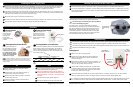


Choosing a Location for the Antenna
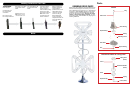
Clearance Requirements
Front of Antenna Mounting Bracket
Other Hardware
Top View
Side View
Install in dry conditions only!
Before choosing a location for the antenna, contact your RV dealer or manufacturer. Your RV may be pre-wired or have a
reinforced area for this system.
When choosing a location for the antenna, keep in mind that the antenna must be mounted on or parallel to the
centerline of the coach with the front of the antenna (the mounting bracket) facing the front of the RV.
Choose a location on the roof of the RV that meets the following requirements:
Offers enough support for a secure installation
Has a minimum roof space (clearance) of 125.3 cm x 43.2 cm
for the stowed antenna
Allows antenna to raise and rotate without interference
from other roof-mounted equipment
• clearance distance of 61 cm from antenna to the front of the vehicle
• clearance radius of 116 cm needed for antenna to raise to vertical position
• clearance distance of 26 cm needed from antenna to nearest obstruction and to the edge of the roof
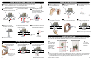
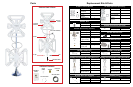
Is within five degrees of level (for best operation, must be within three degrees of level)
• For sloped/rounded roofs, Winegard recommends model RW-2000 exterior roof
wedge (sold separately) to level installation.
• An interior wedge, IW-5000 (sold separately), is also available.
1
4
3
2
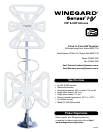
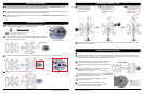
The Winegard Sensar
HV antenna requires a
minimum roof space of
125.3 cm x 43.2 cm for the
stowed antenna.
When stowed, the top of
the element housing rests
11.2 cm above the roof.
The antenna requires a
clearance radius of 115.6 cm
for the antenna to raise to
the vertical position.
Maintain a minimum
distance of 26 cm from the
nearest obstruction and from
the edge of the roof.
26 cm to nearest obstruction
26 cm to edge of roof
Front of RV
Coax cable
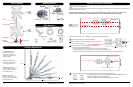
1 Winegard Sensar HV Antenna
Upper
element
housing
43.2 cm
26 cm to nearest obstruction
61 cm to
front of RV
Winegard Sensar HV Antenna 2
Front of RV
RW-2000
Sold Separately
IW-5000
Sold Separately
Centerline of Coach
Front of Antenna
Boom
Lower
element
housing
Weather boot
Mounting bracket
Rotating
gear housing
Base Plate
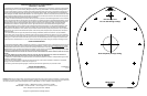
Rotating
gear housing
Leveling
bracket
Power Supply
Directional Handle
Decal
Elevating
Crank
Ceiling Plate
Spring
Nylon Bearing
Bottom of
gear housing
Elevating
Shaft
Base Plate
NOTE
The antenna is
shown in the
travel/stowed position.
125.3 cm
11.2 cm
115.6 cm
125.3 cm