


Raising Antenna Turning on Power Supply
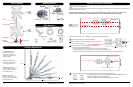
TEST POINT #1
+12 VDC at Antenna
2nd Set
No +12 VDC
at this point
+12 VDC
TEST POINT #2
+12 VDC at
Antenna Jack
Ground
Do not install couplers, splitters, etc. between the power supply and the antenna. Installation of any item on the
downlead may cause a short in the system. The downlead supplies +12 VDC to the preamp in the antenna.
The power supply should be turned OFF when connecting/disconnecting cables to power supply and antenna but
should be turned ON when testing for voltage.
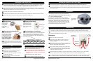
Testing System
Make sure TV set is working properly.
Switch power supply ON and OFF while checking for
difference in picture quality. If there is no difference,
continue with step 3.
Disconnect the cable from the antenna, and check for +12
VDC at Test Point #1. If there is +12 VDC at Test Point #1,
there may be a problem with the antenna.
If there is NO +12 VDC at Test Point #1, reconnect cable
to antenna. Remove power supply from wall, and visually
inspect for burned/broken parts. If there are ANY broken/
burned parts, replace power supply.
Disconnect cable from antenna jack on power supply. Check for +12 VDC at Test Point 2. If +12 VDC is present,
there is a problem with the cable connecting the power supply to the antenna. Repair/replace cable.
If +12 VDC is not present at Test Point # 2, be sure the green indicator light is ON. If not, check the polarity of the ground
and +12 VDC source wires to make sure there are 12VDC present. If there is still no +12 VDC, replace power supply.
Lubricate gears 3–4 times a year for optimal performance.
Use silicone spray to lubricate gears. Never use WD-40
oil for it will damage the gears!
3–4 times a year or in the event that rotating the antenna
becomes difficult, use silicone spray to lubricate the elevating
gear. Apply a liberal amount of silicone spray lubricant to the
elevating gear. The lift should be in the down position. Then,
run the lift up and down to distribute the lubricant over gears.
(This is easiest if one person cranks up and down from inside
the vehicle while another person sprays the gears.)
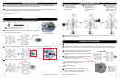
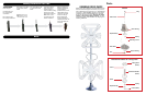
Maintenance
Operation
Turn the elevating
crank clockwise
in “UP” direction
about 13 turns
or until some
resistance to turning
is noted.
Turn power supply on to
use either front or rear
output of the TV outlet.
Neither outlet will work
unless the power supply
switch is on.
1
2
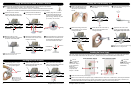
Rotating Antenna for Best Picture Lowering Antenna to Travel Position
Make sure the antenna is in
the “UP”/deployed position.
Pull down with both hands
to disengage ceiling plate.
For analog signals, rotate
for best picture. For digital
signals, run a channel scan
to find the best signal.
Rotate the antenna until the pointer on the directional handle
aligns with the pointer on the ceiling plate. Turn elevating
crank counterclockwise in the “DOWN” direction about 13
turns or until some resistance is noted. The antenna is now
in the travel position.
3
4
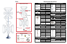
Do
Don’t
Check parking location for obstructions before
raising the antenna.
Carefully raise, lower, and rotate the antenna. If
having trouble, check for obstructions.
Rotate slowly when selecting a station, and check
the fine-tuning on the TV.
Lower the antenna to the travel position before
moving the vehicle.
1
2
3
4
Don’t force the elevating crank up or down or rotate
the directional handle hard against stops.
Don’t travel with the antenna in the up/deployed
position. Stow the antenna before traveling or when
wind speeds reach +113 km/h, or you will void your
warranty.
Don’t leave the antenna partially deployed.
Don’t apply sealant over the top of the base plate.
1
2
3
4
Tune the television receiver to the nearest station, and rotate the antenna for the best picture and sound.
This unit is equipped with a polyswitch, a current limiting device, which will shut down +12 VDC if there is a direct
short between the antenna and power supply. The green indicator light will not light. Once short is eliminated, the
device will reset itself.
Checking the Operation of the Power Supply
1
2
Troubleshooting
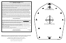
NOTE
Antenna reception may vary based on transmitting antenna tower
height, lobe pattern of the transmitter, height of the receiving
antenna, weather conditions and terrain on receiving path including trees,
buildings and hills.
1
2
3
4
5
6
Installing the Power Supply, Cont.
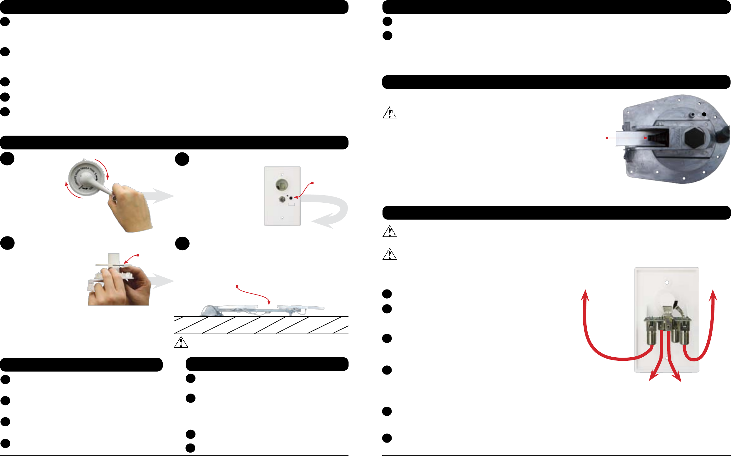
Connect the coax cable from the antenna to the “ANTENNA” port on the power supply, and tighten until fingertight.
(The coax cable should have been routed through the ceiling and wall to the chosen wall plate location.) If the
connector is removed before routing the coax cable, see page 9 for help re-installing the connector.
If hooking up the antenna to a second television, connect another coax cable from the “SET 2” port on the back of the
power supply to the “Antenna In” port on the second television. If hooking up a cable input, connect the cable from the
cable input to the “CABLE” port on the back of the power supply.
Mount the power supply in wall with the provided screws.
Connect the 72” coax cable from the coax port on the front of the power supply to the “Antenna In” coax port on the TV.
Press the “ON” switch on the front of the power supply, and check that the light is on.
3
4
5
6
7
15
/
16
” Cap
7 Winegard Sensar HV Antenna Winegard Sensar HV Antenna 8
ON OFF
On/Off Button
Lower the antenna to the travel position before traveling!
Ceiling
Plate
Lubricate here
around elevating
gear