


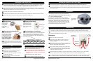


Cutting the Directional Handle to fit Roof Thickness
Carefully align the keys inside
the directional handle with the
keyways on the bottom of the
gear housing. (The keys only line
up one way—do not force.)
Pull the handle down, and transfer
this dimension to the shaft end of
the directional handle. Mark this,
and cut the handle at the mark.
Push the directional handle up
into ceiling and over the shaft.
Measure the distance between
the bottom of the recess on the
handle to the ceiling.
Inside the vehicle, mark the
elevating shaft 3.8 cm below the
ceiling. Cut the shaft on this mark.
Make sure the top of the
directional handle is snug against
the bottom of the base plate.
Determine the roof thickness. The mount is designed to fit roofs from 2.5 cm to 12 cm thick.
• If the roof is less than or equal to 12 cm thick, continue to step 2.
• If the roof is more than 12 cm thick (max. 17.8 cm), a directional handle extension is needed.
Winegard recommends model EK-1036 directional handle extension (sold separately).
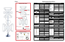
Do not
connect high
current devices
such as hair dryers
to this receptacle.
Maximum
current rating of
receptacle is 8
amps at +12 VDC.
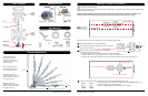
The power supply may be flush mounted in most standard electrical boxes. To flush mount, cut a hole in the wall to fit the
box. Run two #12 wires between the wall plate and +12 VDC source, and route downlead cable to this location.
Select a location for the power supply.
Make 12 volt connection to the power supply. Install terminals on wires from +12 VDC source, and crimp the terminals
with an appropriate crimping tool. If in doubt as to the polarity of the wires, connect them temporarily to the tabs, and
press the “ON” switch on front of wall plate; if light comes on, polarity is correct. Turn power off.
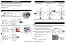
Installing the Crank Assembly
Lay the ceiling plate on top of
the directional handle with
the pointers aligned.
Slide the ceiling plate and
directional handle assembly over
the rotating base shaft.
Installing the Crank Assembly, Cont.
1
2
Make pilot holes in the ceiling.
Then, mount the ceiling plate with
the four provided screws.
3
TIP
The knobs on the
directional handle
should fit into the grooves
on the ceiling plate.
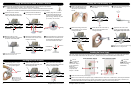
Slide the elevating crank (with
nylon bearing on top) onto the
rotating base shaft.
Check that the set screw lines up
with one of the flat sides of the
rotating base shaft.
7 8
Tighten the set screw until it
touches the rotating base shaft.
Then, tighten only ¼ turn more.
9
NOTE
The set screw simply holds the elevating
crank to the rotating base shaft.
Installing the Power Supply
1
2
2 3 4
5 6 7
TIP
The pointer on the handle should point
toward the back of the coach.
The handle cut
must be flat.
1
The power
supply
should be turned off
when connecting
cables/wires.
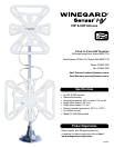
5 Winegard Sensar HV Antenna
Winegard Sensar HV Antenna 6
Front of Power Supply Back of Power Supply
Pointers
3
4
6
2
5
5
7
Set
screw
Thick key
3.8 cm
below ceiling
Cut shaft here
distance x
Cut handle here
distance x
EK-1036
Sold Separately
Remove the backing from the
decal, and place the decal on
the bottom of the directional
handle.
Slide the spring over the rotating
base shaft.
4 5
Place the nylon bearing over the
top of the crank.
6
Thin key
Directional
handle