Making Cable Entry Holes
Assembling the Antenna
The ceiling plate will be mounted inside the vehicle directly underneath the mounting bracket. Make sure the
ceiling area is clear underneath the chosen location for the mounting bracket.
Use the template on the last page of this manual, and drill a 4.5 cm hole through the roof and ceiling of the vehicle.
Be careful not to damage any wiring between the roof and ceiling when drilling.
Using the template on the back page, drill a 13 mm hole for cable entry through the roof of the vehicle only. Do not
drill through the ceiling!
1
2
3
1
2
3
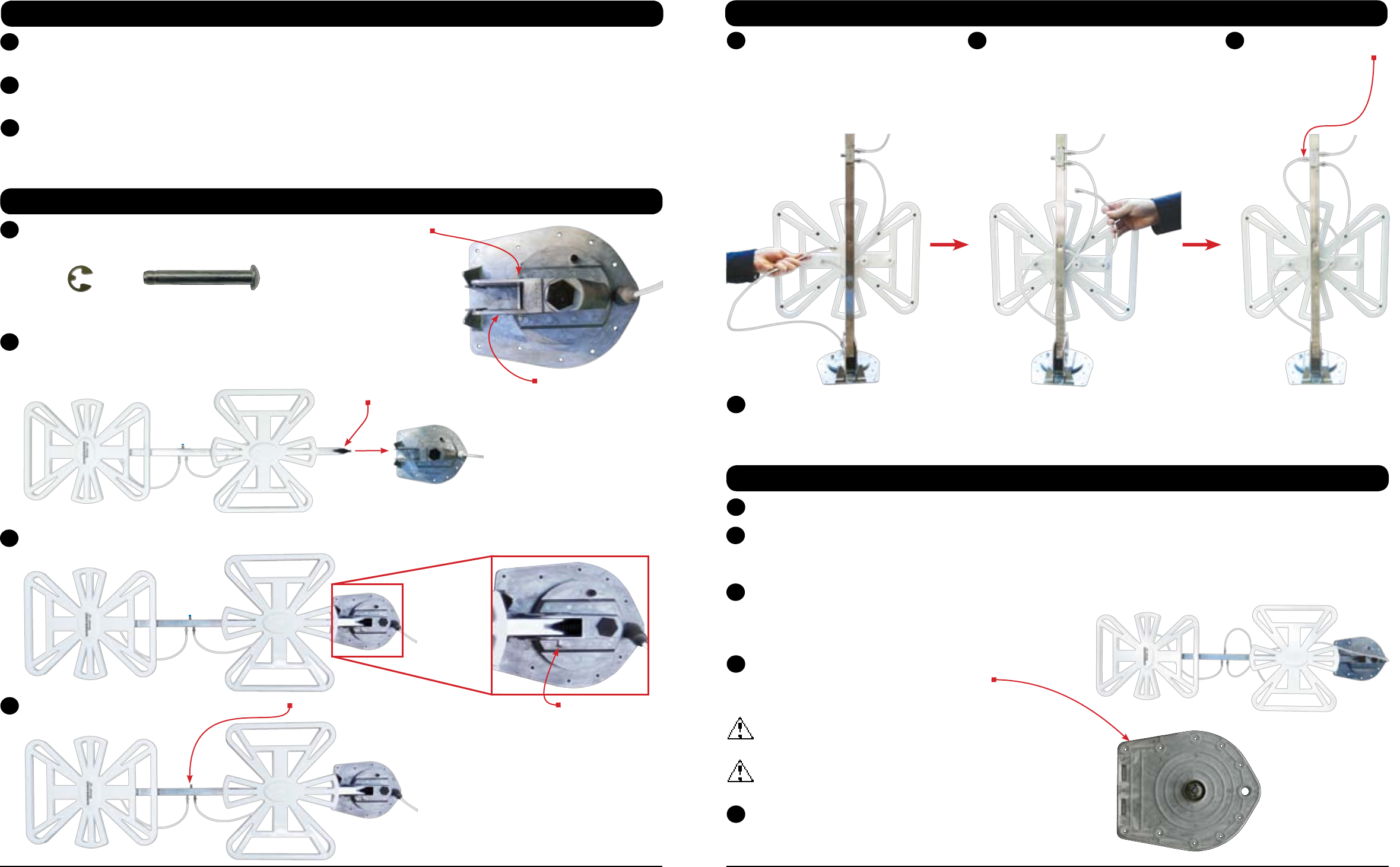
Thread the 140 cm coax
between the boom and
the center of the bottom
element housing.
4
5 6 7
Pull the e-clip off of the pin, and remove the pin from the leveling bracket.
Set the e-clip and the pin aside—you will need these later.
NOTE
An extra e-clip has been provided, which is in
a bag attached to the back of the boom.
With the elements on top of the boom, insert the elevating gear in-between
the sides of the leveling bracket. The holes in the sides of the leveling bracket
and the elevating gear should align.
Insert the pin through the leveling bracket and the elevating gear. Push the e-clip over the end of the pin.
Remove the cap from the coax connection port.
If using a roof wedge or interior wedge, put in place before proceeding to install the base plate or interior hardware.
Center the elevating shaft in the 4.5 cm diameter hole. Check with your vehicle manufacturer to determine if the
provided screws are suitable for your roof. Temporarily secure the base plate to the roof with two of the provided
screws. Check that the weather boot is in place over the boot collar.
Make sure the antenna is in the chosen location. The antenna
should be in the stowed/travel position. The coax cable
should be routed through the ceiling and wall to the power
supply.
Apply a liberal amount of approved nonhardening sealing
compound on the bottom of the base plate.
This will help to prevent leaks.
Do not get sealing compound on bearing surface between
base plate and rotating gear housing.
Do not paint the top of the base plate or around the
rotating gear housing.
Using the provided screws, secure the base plate to
the roof. Run a solid bead of sealant over the mounting
screws. This will also help to prevent leaks.
Installing the Mounting Bracket
1
2
3
5
TIP
Run sealant around
the holes for
the mounting screws,
around the hole for cable
entry, and around the
bottom gear housing.
Assembling the Antenna, Cont.
4
Connect the other end of the 140 cm coax to the 6.1 m coax using a barrel connector, and route the 6.1 m coax to
the location of the power supply.
8
3 Winegard Sensar HV Antenna Winegard Sensar HV Antenna 4
Continue to thread the
coax in an S-curve
between the boom and
the bottom element
housing.
Connect the coax to the
coax connection port,
and tighten until
fingertight. Then,
tighten ¼ turn more.
E-clip Pin
Elevating gear
Travel Position
Leveling bracket
Pin
