


Hydraulic Installation 9
MAN0572 (Rev. 1/30/2009)
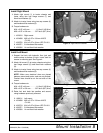
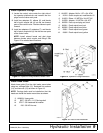
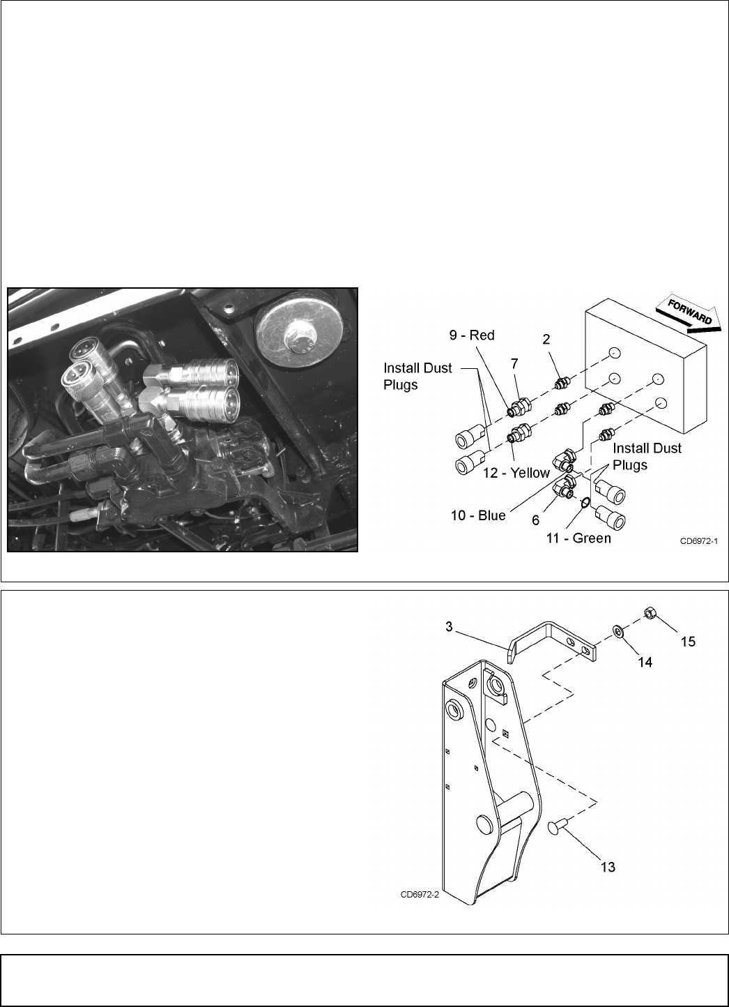
Install Hydraulic Fittings
1. Locate the control valve under the right side of
the operator platform/cab and remove the four
plugs from the valve work ports.
2. Install two adapters (2), elbows (6), and female
half of quick coupler set (4) into the two forward
ports of the control valve. Position elbows to point
forward.
3. Install two adapters (2), adapters (7), and female
half of quick coupler set (4) into the two rear ports
of the control valve.
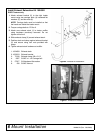
NOTE: Install colored bands and dust plugs
between female quick coupler and fittings. See
Figure 12 for colored band locations.
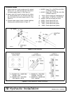
2. 1012055 Adapter, M18 x 1.5P x 3/4 JICM
4. 26124 Quick coupler set, male/female 1/2
6. 313053 Elbow, 1/2 NPTM x 3/4 JICF 90°
7. 315058 Adapter, 1/2 NPTM x 3/4 JICF
8. 395058 Dust cap and plug set, black
9. 395061 Plastic spiral band, red
10. 395062 Plastic spiral band, blue
11. 56061 Plastic spiral band, green
12. 56062 Plastic spiral band, yellow
Figure 11. Hydraulic Fitting Installed, Bottom View
Figure 12. Hydraulic Fitting Installation
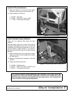
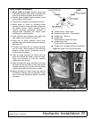
Install Hose Guide
Attach hose guide (3) to the right loader mount shoe
using two carriage bolts (13), hardened flat washers
(14), and hex nuts (15) as shown in Figure 13.
NOTE: Carriage bolts must be installed so that the
heads are inside the loader mount shoe as shown.
3. 1020934 Hose guide
13. 5607 5/8 NC x 1-1/2 Carriage bolt
14. 57817 5/8 Hardened flat washer
15. 230 5/8 NC Hex nut
Figure 13. Hose Guide Installation
DP8A