6 INSTALLATION
MAN0047 (9/15/00)
SUB-FRAME INSTALLATION Cont’d
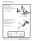
Install Right and Left Rear Supports
Right Rear Support #1001380
Left Rear Support #100381
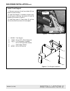
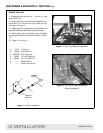
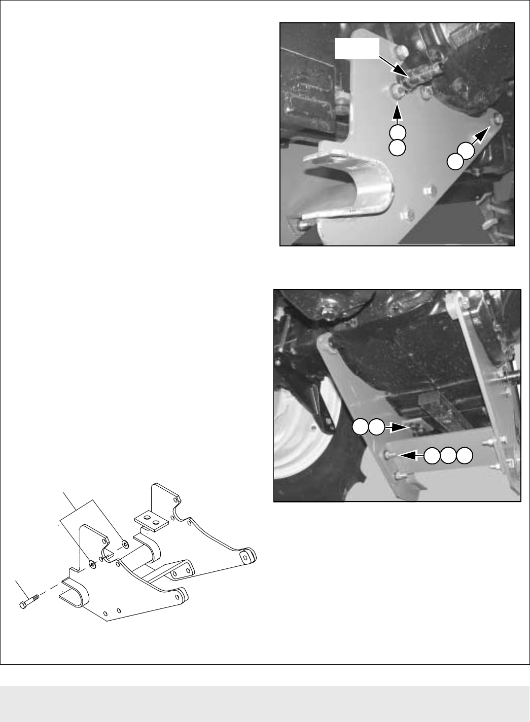
1. Install right rear support by inserting cap screw
(1) and flat washers (2) into position as shown in
Figure 6.
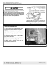
NOTE: Install flat washers between rear support
and pivot pin and on outside at head of cap screw
as shown in Figure 5.
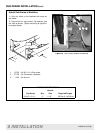
2. Install cap screw (3) and flat washer (2) in front
hole(Figure 6). Only use one flat washer on outside
at head of cap screw.
3. Install remaining two cap screws (1) and four
flat washers (2) into position around pivot pin. Install
flat washers both inside and outside of rear sup-
port.
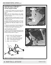
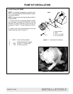
4. Install two cap screws (4) and flat washers (5)
into bottom of tractor chassis as shown in Figure 7
5. Install left rear support, following steps 1-5.
Install Cross Member #1001387
6. Install cross member between right and left rear
supports using four cap screws (3), flat washers (2)
and hex nuts (6) as shown in Figure 7.
1. 1001575 M14 x 2.0P x 55mm Cap screw
2. 46070 9/16 Flat washer, hardened
3. 33125 M14 X 2.0p X 50 mm Cap screw
4. 30743 M16 x 2.0P x 45mm Cap screw
5. 57817 5/8 Flat washer, hardened
6. 307825 M14 x 2.0P Hex nut
Figure 5 Flat Washer Installation on Rear Support
Figure 6 Right Rear Support Installed
Figure 7 Rear Supports & Cross Member Installed
1
2
1
2
3
2
Pivot Pin
4
5
3
2
6


