Audio input and output
By default, the audio ties follow the video ties. Audio breakaway, which can be activated
via the optional front panel or under Ethernet or RS-232 control, allows you to select from
any one of the audio input sources, regardless of video group, and route it separately from
its corresponding video source. See the “Operation” section, the “Programming Guide”
section, the “Matrix Software” section, and the “HTML Operation” section for details.
NOTE: Audio ties can be made only to outputs in the computer/audio subgroup
(outputs 1 through 6).
Audio inputs (either input subgroup)
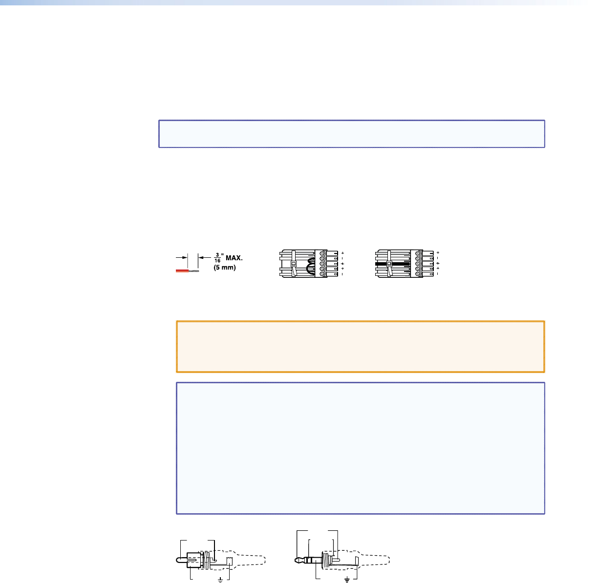
h Connections for balanced and unbalanced audio inputs — Each input has a 5-pole,
3.5 mm captive screw connector for balanced or unbalanced stereo or mono audio
input. Connectors are included with each switcher, but you must supply the audio cable.
See gure 3 to wire a connector for the appropriate input type and impedance level. Use
the supplied tie-wrap to strap the audio cable to the extended tail of the connector.
LR
Unbalanced Stereo Input
Balanced Stereo Input
Ring
Sleeve (s)
Tip
Sleeve
Tip
Sleeve
Tip
Tip
Ring
Do not tin the wires!
Figure 3. Captive Screw Connector Wiring for Stereo Audio Inputs
CAUTION: The captive screw audio connector can easily be inadvertently plugged
partially into one receptacle and partially into an adjacent receptacle.
This misconnection could damage the audio circuits. Ensure that the
connector is plugged fully and only into the correct input or output.
NOTES: • The length of exposed wires is critical. The ideal length is 3/16 inch (5 mm).
• If the stripped section of wire is longer than 3/16 inch, the exposed
wires may touch, causing a short circuit.
• If the stripped section of wire is shorter than 3/16 inch, wires can be
easily pulled out even if tightly fastened by the captive screws.
• Figure 4 identifies the tip, ring, and sleeve. A mono audio connector
consists of the tip and sleeve. A stereo audio connector consists of the
tip, ring and sleeve. The tip, ring, and sleeve wires are also shown on
the captive screw audio connector diagrams (see figure 3, above, and
figure 5 on the next page).
Tip (+)
Sleeve ( )
Sleeve ( )
Ring (
-
)
Tip (+)
RCA Connector
3.5 mm Stereo Plug Connector
(balanced)
Figure 4. Typical Audio Connectors
The audio level for each input can be individually set at the front panel or via Ethernet
or RS-232 control to ensure that the level on the output does not vary from input to
input. See the “Operation” section, the “Programming Guide” section, the “Matrix
Software” section, and the “HTML Operation” section for details.
MPX 866 A Media Presentation Matrix Switcher • Installation 9


