Serial Ports
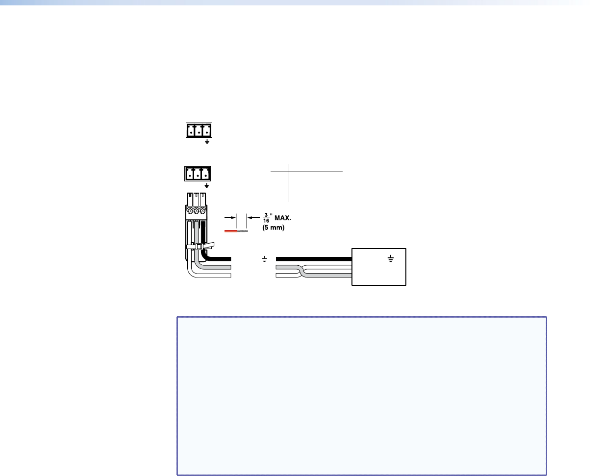
j RS-232 connectors — Connect one or two host devices, such as computers, touch
panel controls, or RS-232 capable PDAs to the switcher via these 3-pole captive screw
connectors for serial RS-232 (see gure 6). Use the supplied tie-wrap to strap the serial
cable to the extended tail of the connector.
FunctionPin
TX
RX
Gnd
Transmit data
Receive data
Signal ground
PRIMARY
RS-232
SECONDARY
Tx Rx
Tx Rx
Controlling
Device
Ground ( )
Receive (Rx)
Transmit (Tx)
Ground ( )
Receive (Rx)
Transmit (Tx)
Bidirectional
Do not tin the wires!
Figure 6. RS-232 connector
NOTES: • The length of exposed wires is critical. The ideal length is 3/16 inch
(5 mm). See the audio input connector NOTES for more information.
• These two ports are hardwired for RS-232 only.
• The RS-232 Secondary port is active only if the front panel Configuration
port is not in use. If a front panel configuration connection is made, the
rear panel RS-232 Secondary port becomes inactive and the front panel
Configuration port is active.
• The switcher can operate at 9600, 19200, 38400, or 115200 baud rates.
See “Selecting the Baud Rate of the RS-232 Primary Port” in the
“Operation” section to configure the RS-232 Primary port from the front
panel. See the Set serial port parameters SIS command to configure all
ports under SIS control.
See “Programming Guide” for definitions of the SIS commands (serial commands to
control the switcher via this connector) and “Matrix Software” for details on how to
install and use the control software.
If desired, connect an MKP 2000 or MKP 3000 remote control panel to the RS-232
connector of the switcher. See the MKP 2000 Remote Control Panel User Guide or the
MKP 3000 Remote Control Panel User Guide for details.
MPX 866 A Media Presentation Matrix Switcher • Installation 11


