22
Rear Panel
Chapter 2 Names and Functions of Parts
i MAINTENANCE connectors
These are the USB connectors for maintenance.
Do not connect USB devices to this unit for any purpose
other than maintenance.
j SDSDI OUTPUT 1, 2 (SUPER) (SDI signal outputs
1, 2 (superimpose)) connectors (BNC type)
These output SDSDI format video/audio signals.
When the unit is shipped from the factory, audio signal
output is eight channels with no switching, and RP188
timecode output is set to on. You can change these settings
with setup menu item 828 SDI AUDIO OUTPUT
SELECT and setup menu item 920 SD-SDI H-ANC
CONTROL.
The output from the 2 (SUPER) connector can have
timecode, menu settings, alarm messages, and other text
information superimposed. To turn superimposition off,
set CHAR SEL on the HOME page of the function menu
to “OFF”.
See “Items in the extended menu” (page 96) for more
information.
See “Basic Operations of the Function Menu” (page 39)
for more information.
1 Power supply section
a POWER (main power) switch
Press the : side to power on the unit. Press the a side to
power off.
When using the unit, normally leave the POWER switch in
the : (on) position, and use the on/standby button on the
front panel to switch the unit between the operating state
and standby state.
Before turning the main power off, always check to be sure
that the unit is in the standby state, and then press the main
power switch to the a side.
b -AC IN connector
Connect to an AC power supply with the power cord (not
supplied).
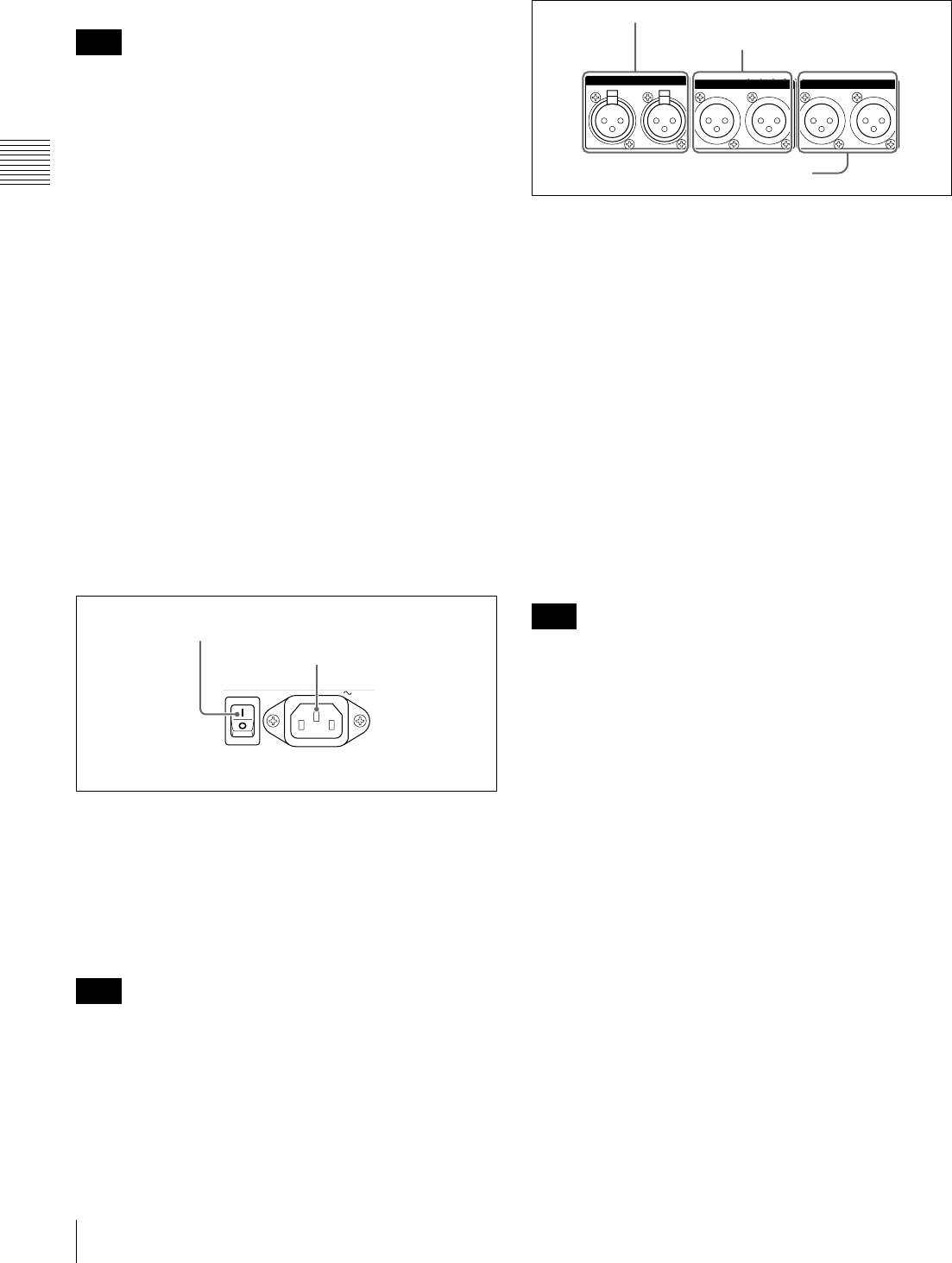
2 Analog audio signal input/output section
a ANALOG AUDIO INPUT 1, 2 connectors (XLR 3-
pin, female)
These input analog audio signals.
With A1 INPUT or A2 INPUT on page P2 AUDIO, and
A3 INPUT or A4 INPUT on page P3 AUDIO of the
function menu (see page 41), you can select whether the
signal input to connector 1 is assigned to audio channel 1or
3, and whether the signal input to connector 2 is assigned
to audio channel 2 or 4.
You can set the reference input level with the maintenance
menu item M37: AUDIO CONFIG (see page 108).
(Factory default setting: +4 dB)
Microphone settings
If you have connected a microphone to this unit, you can
set input level, AGC, and limiter values for the
microphone with setup menu items 834, 839, 840, and 841
(see page 105).
An unpleasant sound may be output if you have connected
a microphone to the ANALOG AUDIO INPUT 1 or 2
connector and power the microphone on with the input
level too high. Check the input level setting before
connecting a microphone.
b ANALOG AUDIO OUTPUT 1, 2 connectors (XLR
3-pin, male)
These output analog audio signals.
When the unit is shipped from the factory, the 1 connector
is set to audio channel 1, and the 2 connector is set to audio
channel 2. You can change these settings with setup menu
item 824 ANALOG LINE OUTPUT SELECT (see
page 104).
You can set the output level with the maintenance menu
item M37: AUDIO CONFIG (see page 108). (Factory
default setting: +4 dB)
Non-audio signals are muted.
c AUDIO MONITOR R, L connectors (XLR 3-pin,
male)
This outputs an audio signal for monitoring.
The monitored channel is selected with MONITR L and
MONITR R on page P2 AUDIO of the function menu.
Note
Note
POWER
AC IN
1 POWER switch
2 - AC IN connector
Note
ANALOG AUDIO INPUT
ANALOG AUDIO OUTPUT
1212
AUDIO MONITOR
RL
1 ANALOG AUDIO INPUT 1, 2 connectors
2 ANALOG AUDIO OUTPUT 1, 2
connectors
3 AUDIO MONITOR R, L connectors


