


78-9000-0192-2 Rev C 13
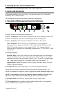
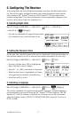
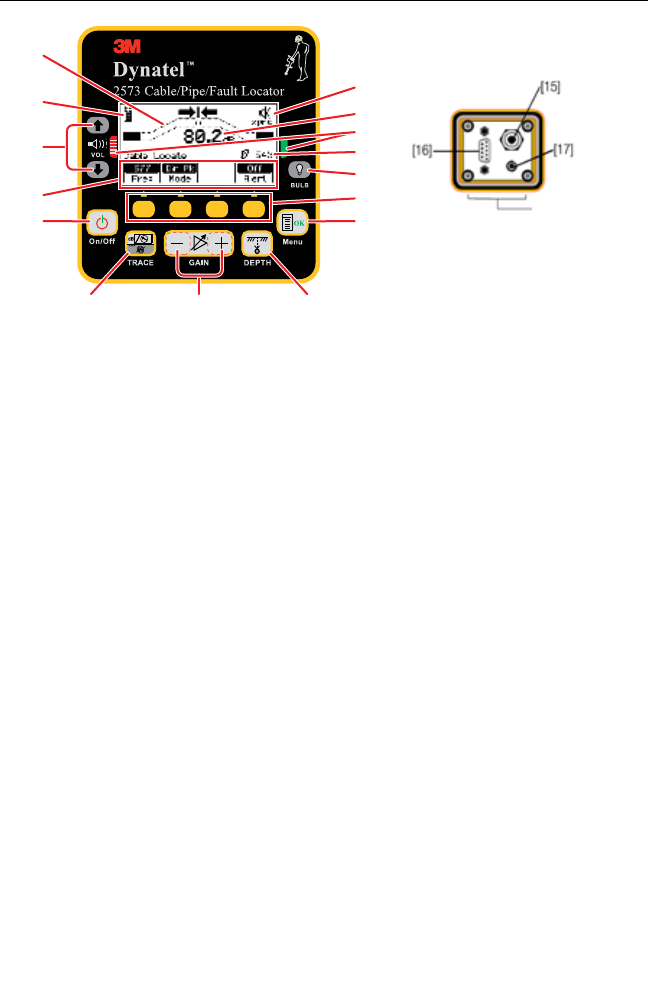
[15] Serial Port: RS232 port to connect the receiver to a PC via serial cable or USB-to-
Serial Adapter cable.
[16] Earphone Jack: Will fit standard 1/8 inch (3.175 mm) mini-jack mono earphone
plug (not included).
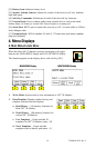
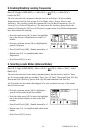
J. 2573 Receiver Keypad and Display Definitions
[11]
[12]
[13]
[14]
[1]
[10]
[9]
[8]
[7]
[6]
[5]
[SK]
[2] [3] [4]
Access panel on
bottom side of
Receiver
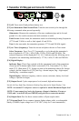
[1] On/Off (Power): Turns unit on and off.
[2] TRACE (Locate) MODE: Toggles between Cable View locate mode and the four
other locate modes (cycles through available modes via the Mode soft key when in the
Cable/Pipe Locate display.
[3] GAIN: Adjusts the sensitivity of the receiver either up (+) or down (-) to maintain a
satisfactory signal level.
[4] DEPTH: Measures depth of target.
[5] Menu / OK: Sets the receiver to trace mode for locating cable or pipe and displays
Locate options, 3M iD Marker templates and writing mode options, setup screens for
configuration of the unit, i.e.: clock, language, depth units, marker data and frequencies,
COM settings and Help files. Also acknowledges setup entries (OK).
[SK] Soft Keys: There are four soft keys (yellow keys) on the receiver. The function
of each key is shown above the yellow key on the display screen. The functions will
change, depending on the operation mode of the receiver. For instruction purposes in this
manual, the display command is followed by [SK] to identify it as a soft key.
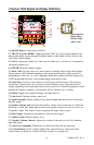
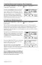
[6] BULB: Toggles the display backlight low, high, and off.
[7] Gain Level: Displays relative gain level.
[8] Fault Finding Direction Indicators: Corresponds to the Earth Contact Frame
(A-Frame) probe (leg) colors.
[9] Signal Strength: Digital reading of the signal strength that the receiver is detecting
from the target.
[10] Speaker Volume Icon: Indicates the relative volume level of the receiver. When the
third ring is dotted and ‘xpnd' appears below the speaker volume icon, the receiver is in
“Expander” mode. This mode is used to pinpoint the target cable or pipe.
[11] Bar Graph: Graphical representation of the received signal.