


78-9000-0192-2 Rev C 59
19. Additional Applications
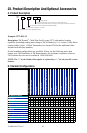
A. Aerial Faults (Toning) (3M
™
Dynatel
™
Models 2573 and 2573-iD only)
Transmitter Setup
Step 1. Connect the transmitter (based on type of fault) as described in Connection
Diagrams in the following section.
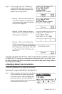
Step 2. Press and hold off [T-1] to perform a battery test.
Step 3. Press on: Ohm-meter/Faul Locate/Tone [T-2] to power the Transmitter on and
to verify the fault.
Step 4. Press on: Ohm-meter/Faul Locate/Tone [T-2] twice more to select the Tone
mode.
Step 5. The Digital Display [T-4] will alternately flash between 577 and 200K.
Step 6. Press Output Level [T-5] for high or maximum output level.
Receiver Setup
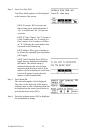
Step 1. Press On/Off [1] to turn the receiver on.
Step 2. Press Menu/OK [5:Toggle to MAIN MENU]
Step 3. Press Tone/Ext [SK] to select Tone mode.
Step 4. Press Freq [SK Toggle] to select 577Hz.
Step 5. Connect a toning coil to the receiver External Jack [15] ([14] for 2550 locator).
Step 6. Move the toning coil along the cable and find a peak signal then press Gain [3]
down to adjust the receiver gain.
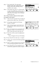
Step 7. Press Speaker Volume Control [13] ([12] for 2550 locator) to adjust the speaker
volume as needed.
Step 8. Follow the cable with the toning coil.
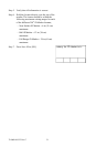
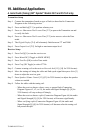
− When the receiver detects a short, cross, or ground fault (Connection
Diagram Figures #1, #2, or #3), the audio and Signal Strength [9] ([8] for
2550 locator) will stop or drop off sharply.
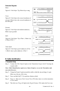
− When the receiver detects a split (Connection Diagram Figure #4) the audio
and Signal Strength [9] ([8] for 2550 locator) will increase significantly.
− When verifying a split (Connection Diagram Figure #5) the audio and
Signal Strength [9] ([8] for 2550 locator) will decrease after the toning coil
has passed the split.