


Chapter 1 49
Making Basic Measurements
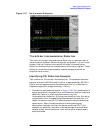
Measuring Signal-to-Noise
Measuring Signal-to-Noise
The signal-to-noise measurement procedure below may be adapted to
measure any signal in a system if the signal (carrier) is a discrete tone.
If the signal in your system is modulated, it will be necessary to modify
the procedure to correctly measure the modulated signal level
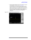
In this example the 50 MHz amplitude reference signal is used as the
fundamental source. The amplitude reference signal is assumed to be
the signal of interest and the internal noise of the analyzer is measured
as the system noise. To do this, you will need to set the input attenuator
such that both the signal and the noise are well within the calibrated
region of the display.
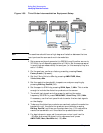
Signal-to-Noise Measurement Example:
Perform the steps below to measure the signal-to-noise.
1. Perform a factory preset by pressing Preset, Factory Preset (if
present).
2. Turn on the internal 50 MHz amplitude reference signal of the
analyzer as follows:
• For the E7401A, use the internal 50 MHz amplitude reference
signal of the analyzer as the signal being measured. Press
Input/Output, Amptd Ref (On).
• For all other models connect a cable between the front-panel
AMPTD REF OUT to the analyzer INPUT, then press
Input/Output, Amptd Ref Out (On).
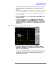
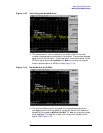
3. Set the center frequency to 50 MHz by pressing FREQUENCY,
Center Freq, 50, MHz.
4. Set the span to 1 MHz by pressing SPAN, Span, 1, MHz.
5. Set the Y-Axis Units to dBm by pressing AMPLITUDE, More,
Y-Axis Units,
dBm.
6. Set the resolution bandwidth to spectrum analyzer coupling by
pressing BW/Avg, Res BW (SA).
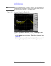
7. Set the reference level to –10 dBm by pressing AMPLITUDE, Ref Level,
–10,
dBm.
8. Set the attenuation to 40 dB by pressing AMPLITUDE, Attenuation, 40,
dB.
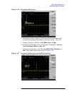
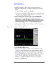
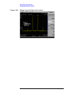
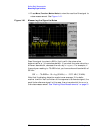
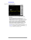
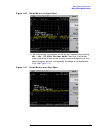
9. Press Peak Search to place a marker on the peak of the signal.
10.Press Marker, Delta, 200, kHz to put the delta marker in the noise at
the specified offset, in this case 200 kHz.