


Chapter 2 85
Making Complex Measurements
Making a Reflection Calibration Measurement
Reflection Calibration
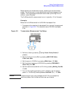
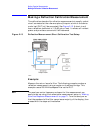
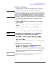
1. Connect the DUT to the directional bridge or coupler as shown in
Figure 2-13. Terminate the unconnected port of the DUT.
NOTE If possible, use a coupler or bridge with the correct test port connector
for both calibrating and measuring. Any adapter between the test port
and DUT degrades coupler/bridge directivity and system source match.
Ideally, you should use the same adapter for the calibration and the
measurement. Be sure to terminate the second port of a two port device.
2. Connect the tracking generator output of the analyzer to the
directional bridge or coupler.
3. Connect the analyzer input to the coupled port of the directional
bridge or coupler.
4. Perform a factory preset by pressing
Preset, Factory Preset (if
present).
5. Set the Y-Axis Units to dBm by pressing
AMPLITUDE, More,
Y-Axis Units,
dBm.
6. Turn on the tracking generator and if necessary, set the output
power to –10 dBm by pressing
Source, Amplitude (On), –10, dBm.
CAUTION Excessive signal input may damage the DUT. Do not exceed the
maximum power that the device under test can tolerate.
7. Set the span to 100 MHz by pressing
SPAN, Span, 100, MHz.
8. Set the center frequency to 200 MHz by pressing
FREQUENCY,
Center Freq, 200, MHz.
9. Set the resolution bandwidth to 3 MHz by pressing
BW/Avg, Res BW,
3, MHz.
10.Replace the DUT with a short circuit.
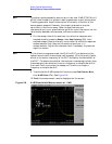
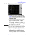
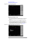
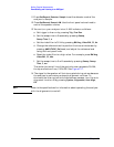
11.Normalize the trace by pressing
Trace/View, More, Normalize,
Store Ref (1→3), Normalize (On). See Figure 2-14.
This will activate the trace 1 minus trace 3 function and display the
results in trace 1. The normalized trace or flat line represents 0 dB
return loss. Normalization occurs each sweep. Replace the short
circuit with the DUT.
NOTE Since the reference trace is stored in trace 3, changing trace 3 to
Clear Write will invalidate the normalization.