


82 Chapter 2
Making Complex Measurements
Making Stimulus Response Measurements
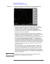
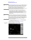
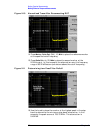
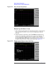
Figure 2-10 Normalized Trace After Reconnecting DUT
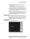
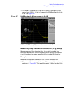
14.Press
Marker, Delta Pair (Ref), 10, MHz to place the reference marker
at the specified cutoff frequency.
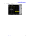
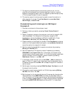
15.Press
Delta Pair (∆), 20, MHz to place the second marker at the
20 MHz point. In this example, the attenuation over this frequency
range is 63.32 dB/octave (one octave above the cutoff frequency).
Figure 2-11 Determining Low Pass Filter Rolloff
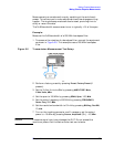
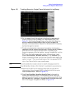
16.Use the knob to place the marker at the highest peak in the stop
band to determine the minimum stop band attenuation. In this
example, the peak occurs at 708.76 MHz. The attenuation is
54.92 dB.