


Chapter 1 59
Making Basic Measurements
Demodulating AM Signals (Using the Analyzer As a Fixed Tuned Receiver)
Demodulating AM Signals (Using the Analyzer
As a Fixed Tuned Receiver)
The zero span mode can be used to recover amplitude modulation on a
carrier signal. The analyzer operates as a fixed-tuned receiver in zero
span to provide time domain measurements.
Center frequency in the swept-tuned mode becomes the tuned
frequency in zero span. The horizontal axis of the screen becomes
calibrated in time only, rather than both frequency and time. Markers
display amplitude and time values.
The following functions establish a clear display of the waveform:
• Trigger stabilizes the waveform trace on the display by triggering on
the modulation envelope. If the modulation of the signal is stable,
video trigger synchronizes the sweep with the demodulated
waveform.
• Linear mode should be used in amplitude modulation (AM)
measurements to avoid distortion caused by the logarithmic
amplifier when demodulating signals.
• Sweep time adjusts the full sweep time from 5 ms to 2000 s. (20 µs to
2000 s if Option AYX is installed). The sweep time readout refers to
the full 10-division graticule. Divide this value by 10 to determine
sweep time per division.
• Resolution and video bandwidth are selected according to the signal
bandwidth.
Each of the coupled function values remains at its current value when
zero span is activated. Video bandwidth is coupled to resolution
bandwidth. Sweep time is not coupled to any other function.
NOTE Refer to “Demodulating and Listening to an AM Signal” on page 88 for
more information on signal demodulation.
To obtain an AM signal, you can either connect a source to the analyzer
input and set the source for amplitude modulation, or connect an
antenna to the analyzer input and tune to a commercial AM broadcast
station.
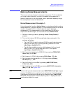
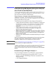
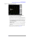
Demodulating an AM Signal Example 1:
View the modulation waveform of an AM signal in the time domain.
1. Connect an RF signal source to the analyzer INPUT. For this
example, an Agilent E4433B Signal Generator was used with the
following settings:
a. RF Frequency 300 MHz