


74 Chapter 2
Making Complex Measurements
Making Stimulus Response Measurements
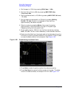
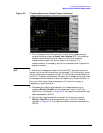
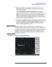
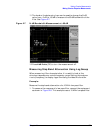
Figure 2-3 Decrease the Resolution Bandwidth to Improve Sensitivity
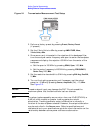
10.You might notice a decrease in the displayed amplitude as the
resolution bandwidth is decreased, (if the analyzer is an E7402A,
E7403A, E7404A, or E7405A). This indicates the need for
performing a tracking peak. Press
Source, Tracking Peak. The
amplitude should return to that which was displayed prior to the
decrease in resolution bandwidth.
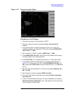
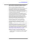
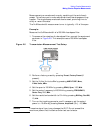
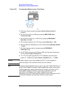
11.To make a transmission measurement accurately, the frequency
response of the test system must be known. Normalization is used to
eliminate this error from the measurement. To measure the
frequency response of the test system, connect the cable (but not the
DUT) from the tracking generator output to the analyzer input.
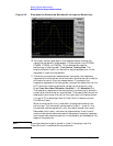
Press
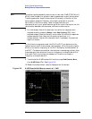
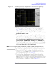
Trace/View, More, Normalize, Store Ref (1→3), Normalize (On).
The frequency response of the test system is automatically stored in
trace 3 and a normalization is performed. This means that the active
displayed trace is now the ratio of the input data to the data stored
in trace 3. (The reference trace is Trace 3 with firmware revision
A.04.00 and later)
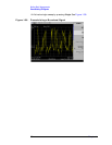
When normalization is on, trace math is being performed on the
active trace. The trace math performed is (trace 1 − trace 3 + the
normalized reference position), with the result placed into trace 1.
Remember that trace 1 contains the measurement trace, trace 3
contains the stored reference trace of the system frequency response,
and normalized reference position is indicated by arrowheads at the
edges of the graticule.
NOTE Since the reference trace is stored in trace 3, changing trace 3 to
Clear Write will invalidate the normalization.