


8
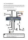
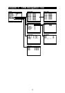
1.5.3 Connecting the Sensor/Relay device
The Sensor and Alarm ports enable you to connect (4) sensor inputs and (1) relay
outputs. Just connect the external sensor and relay pin directly to the pinhole.
Check the table below and locate which pinhole is assigned to sensor input and
relay output.
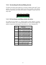
1.5.3.1 I/O Card Sensor and Relay pinhole allocation:
The signal from the sensor (i.e., infrared sensors, smoke detectors, proximity
sensors, door sensors, etc.) is being transmitted to the unit and this triggers the
system to respond and send signal to relay device (i.e., alarm, telephone etc).
Pin # Definition
1 Sensor 1 positive pole signal
2 Sensor 1 negative pole signal
3 Sensor 2 positive pole signal
4 Sensor 2 negative pole signal
5 Sensor 3 positive pole signal
6 Sensor 3 negative pole signal
7 Sensor 4 positive pole signal
8 Sensor 4 negative pole signal
9 Relay negative pole signal
10 Relay positive pole signal