


4
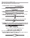
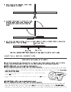
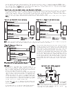
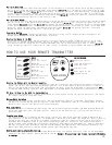
4. Use electrical tape to wrap, be sure to cover about 2 inches on either side of connection.
Secure with wire ties as shown.
3. Lay upper twisted pair of wires over right
wire as shown. Bring lower twisted pair
of wires up to meet the left wire as
shown.
2. Twist upper wires together, twist lower
wires together as shown.
Use this method ONLY when connecting two separate wires end to end.
Wire Tie
Electrical Tape
Wire Tie
LOCATING & MAKING CONNECTIONS
Please see the wiring chart on this website.
Most of the wires you will be using will be in a taped or nylon sleeve coming from the ignition switch.
You must find and remove about six inches of this outer covering for testing and connecting.
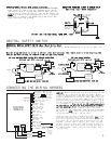
CONSTANT POWER (+12V, key in any position including off)
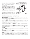
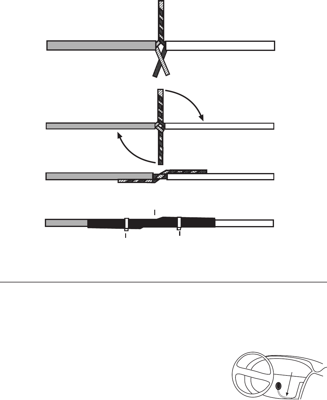
Make all connections as close to the ignition switch as possible.
These wire(s) are in your vehicle’s main ignition harness, usually located in the steering column coming
from the ignition switch. Probe each wire with your provided test probe. The correct wire(s) will show
+12V and the RED light will glow bright on the test probe when the ignition switch is in these 5 positions
(ACC-LOCK-OFF-RUN-CRANK).
IGNITION HARNESS
UNDER DASH
1. If your vehicle has only (1) constant power wire, attach both heavy
gauge RED wires to it.
2. If your vehicle has (2) constant power wires, attach one RED wire to
each.
IGNITION WIRE(S) (+12V in run and crank position only)
Make all connections as close to the ignition switch as possible.
The ignition wire(s) are also located in the main harness coming from the ignition switch. Check your
chart for probable colors and probe each wire with your provided test probe. The correct wire(s) will
show +12V and the RED light will glow bright only when the ignition switch is in the RUN AND CRANK
positions. The correct wires will not show +12V when in the OFF or ACCESSORY position. Most Ford, GM,
and Chrysler vehicles have at least two (2) ignition wires. Most foreign vehicles have only one (1).