


7
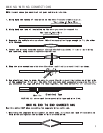
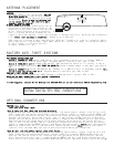
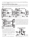
ANTENNA PLACEMENT
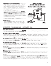
FACTORY ANTI-THEFT SYSTEMS
OPTIONAL CONNECTIONS
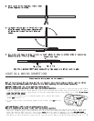
Control Module
Antenna Wire
Antenna Tube
ANTENNA
For best results, run the antenna (YELLOW
WIRE WITH BLACK TIP from the back of the
unit) as high up in the dash and as straight
as possible. Do not place the antenna next
to any metal parts or the vehicle’s main
computer control module.
E MODEL REMOTE STARTERS
Run the antenna up the windshield pillar on
the driver’s side and across the top of the
windshield to the center, behind the rearview
mirror. Use the antenna clips provided to
hold it in place. Be sure to expose the full
FOR GENERAL MOTORS CARS ONLY
System 1: PASSKEY or VATS system (1985 and up). This system has a resistor pill in the key. Measure
resistance of the pill using a test meter. A bypass module is available, part #781 or #791.
System 2: PASSLOCK I and II system (1995 and up). Passlock does not have a pill in the key. It has a
light on the dash that states ANTI-THEFT OR SECURITY system. A bypass module is available, part #781 or
#791.
System 3: PASSKEY III system (GM 1998 and up). Passkey III is GMs version of a transponder system. This
key will have the letters PK3 on it. A bypass module is available, part #781 or #791.
FORD ANTI-THEFT SYSTEM: PATS
1995-1997 Ford uses a bypass part #FBP-718 module. (1998 and up will use part #781 or #791.)
CHRYSLER AND MOST IMPORTS ANTI-THEFT SYSTEM: TRANSPONDER
1998 and up will use part #781 or #791.
To order bypasses, contact Direct Wholesale at 800-659-0764.or see our website at www.bulldogsecurity.com.
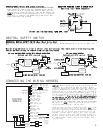
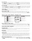
TESTING: Door Locks
There are three basic types:
“Type A” Door Lock Test (Most GMs and some Chryslers)
Probe both of your door lock wires going to the door lock switch usually located in the driver’s kick
panel. Probe the lock and the unlock wires, the test probe will show a (-) negative and the GREEN light
will glow bright on both the lock and the unlock wires. Press and hold the lock button on the switch
and test the lock wire. The correct wire will test (+) positive and the RED light will glow bright.
Release the lock button and this wire should show a (-) negative and the GREEN light will glow bright.
Now press and hold the unlock button on the switch and test the unlock wire. The correct wire will
test (+) positive and the RED light will glow bright. Release the unlock button and this wire should
show a (-) negative and the GREEN light will glow bright. Your vehicle has a “Type A” door locking system.
Make sure to mark which wire is lock and unlock. Connecting Door Locks. NOTE: “Type A” and “Type C”
locks will test the same. Make sure you run both tests before making your connections.
“Type B” Door Lock Test (Most Imports, some newer Fords)
Probe both of your door lock wires going to the door lock switch usually located in the driver’s kick
panel. Probe the lock and the unlock wires, the test probe will glow both GREEN and RED (dimly) on
both the lock and the unlock wires. Press and hold the lock button on the switch and test the lock
wire. The correct wire will test (-) negative and the GREEN light will glow bright. Release the lock
button and this wire should again glow both GREEN and RED (dimly). Now press and hold the unlock button
length of the clear antenna. It will perform best if mounted vertically, below the dark windshield
tint. Never leave antenna in headliner. Range is up to 800 feet.
Each receiver is tested to more than 400 feet (800 feet, E models) of clear air reception. While
many times you will see a higher range. Many factors will affect the range, including the amount
of radio signals in the area, battery
strength, window tint, etc.
START VEHICLE AND CHECK STARTER SYSTEM
BEFORE ADDING OPTIONAL CONNECTIONS.