


5
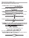
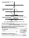
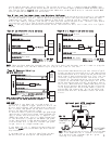
Note: Remove any paint below
the spade connector.
Factory Bolt
Spade Connector
Black Ground Wire
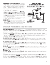
1. If your vehicle has only one (1) ignition wire, as most 1993 and older domestic and import vehicles
do, connect the heavy gauge WHITE wire to it.
2. If your vehicle has two (2) ignition wires, as most 1994 and newer vehicles do, connect the heavy
gauge RED with WHITE stripe wire to the Ignition 2 wire.
3. If your vehicle has three (3) ignition wires, as some newer GMs, Fords and Chryslers do, connect the
heavy gauge WHITE wire to the third ignition along with the Ignition 1 wire.
ACCESSORY WIRE(S) THAT POWER THE HEATER/BLOWER MOTOR
(+12V in run or on positions) This wire is also in the main ignition switch harness. Make this connection as
close to the ignition switch as possible.
Most vehicles will have one (1) accessory wire; however some Fords, newer GM vehicles and Chrysler 94 and up will
have two (2) or more accessory wires. Check your wire color chart and then verify these wire(s).
The correct
wire(s) will show +12V and the RED light will glow bright
when the ignition switch is in the RUN or ON positions.
This wire(s) will not show +12V when the ignition switch is in any other position.
1. If your vehicle has only one (1) accessory wire connect the heavy gauge WHITE WITH BLACK STRIPE wire to this
wire.
2. If your vehicle has two (2) accessory wires, connect the WHITE WITH BLACK STRIPE wire to both accessory wires.
3. If your vehicle has three (3) accessory wires, connect the WHITE WITH BLACK STRIPE wire to all three.
STARTER/CRANK WIRE (+12V in the start position only)
Make all connections as close to the ignition switch as possible.
The starter/crank wire is also in the main harness. Check your chart for probable colors and verify the wire
. The
correct wire(s) will show +12V and the RED light will glow bright
only in the crank position. This wire
will not show +12V in any other position. Attach the YELLOW WITH BLACK STRIPE wire to it.
NOTE: Most Nissans will have two (2) starter/crank wires. Both must be connected to the YELLOW WITH BLACK STRIPE
wire.
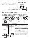
CHASSIS GROUND
Locate an easy to get to bolt or screw located under the driver’s side of the dash and attach the BLACK ground
wire from the 16-pin harness securely as pictured. A good ground is vital for your system to operate correctly.
FACTORY ALARM SHUT DOWN WIRE (FASD) (-)
If your vehicle is equipped with a factory alarm system (as most new model vehicles with a factory keyless
entry are) and you can disarm your factory alarm by using your key in the door. Check the owner’s manual or
contact your dealer to see if your vehicle is so equipped. Probe for a small gauge wire (usually found in
the driver’s side kick panel) that shows (-) ground and the GREEN light will glow bright when the door lock
cylinder is turned to the unlock position using the key and will show +12V and the RED light will glow bright
before turning the key. NOTE: Some factory disarm wires remain neutral (both the GREEN and the RED lights
will be dimly illuminated) before you turn the key to unlock instead of +12v positive. Connect the RED WITH
BLACK STRIPE wire from the 16-pin harness to this wire. See chart, page 21 for listing by manufacturer.
IGNITION OUTPUT (-) (Security bypass output wire)
This wire will be used to operate the security bypass module, VATS-WR, #781 or the #791 module. This
WHITE wire holds a ground output the entire time the remote starter is activated. Connect this wire to
the WHITE wire on the bypass module to control when the bypass is on and off.
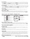
HOOD PIN SWITCH (-)
This feature will keep the engine from starting, or shut off the engine when the hood is opened.
Locate a good chassis ground, if at all possible do not install the pin switch in the rain gutter.
Drill a 5/16 hole, insert the pin switch into the hole and tighten. Check for the hood adjustment,
there is approximately 1/4” adjustment in the pin switch. Close the hood easy, making sure that
the pin switch is not keeping the hood from closing all the way, if it does, cut off approximately
1/8” of the black plastic off of the top of the hoodpin switch and try closing the hood again.
Check to make sure that the hoodpin switch remains neutral when the hood is closed and shows ground
when the hood is open. Route the BLACK WITH BLUE STRIPE wire from the 16-pin harness through the
firewall and connect it to the bottom of the hood pin switch.
BRAKE INPUT (+)
The brake wire is located on the switch near and above the brake pedal.
The correct wire will show +12V and
the RED light will glow bright
only when the brake is pressed. Connect the BLUE WITH BLACK STRIPE from the 16-
pin harness to this wire.
TACH INPUT (Optional)
If you have chosen the TACHLESS start option, simply proceed to the next step and skip the following
instructions. Make sure to tape the BLACK WITH WHITE STRIPE wire if not used. For TACH mode connect
the BLACK WITH WHITE STRIPE wire from the 16-pin harness to the negative side of the coil or the
tach wire at the coil pack under the hood. To find the coil pack follow the spark plug wires back
to their beginning point. To operate in tach mode, make sure to program tach option, see programming
tach option page 10.