


13
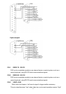
PIN 4. SWITCH OUT
Connect to VCR trigger recording terminal of multiplexer, in order to synchronize
recording signals. The default mode is falling (Negative) Edge.
PIN 5. ERROR OUT
When HDD errors happen, this pin will send a signal out.
This pin become “Low” when HDD errors happen. The normal operation remains
“High”
PIN 6. REC START
This pin can accept the external trigger signal to activate record mode from
external device. When the external signal turn to “Low”, it will trigger DVR record
mode. When the external signal back to “High”, it will stop recording action.
The default normal operation remains “High”.
PIN 7. EXTERNAL ALARM NC
Under normal operation COM connect with NC and disconnect with NO. But when
alarm triggered, COM disconnect with NC, and connect with NO.
PIN 8. EXTERNAL ALARM NO
Under normal operation COM connect with NC and disconnect with NO. But when
Alarm triggered, COM disconnect with NC, and connect with NO.
PIN 9. GND
GROUND
PIN 10. RS485-B
DVR can be controlled remotely by an external device or control system, such as a
control keyboard, using RS485 serial communications signals.
PIN 11. RS485-A
DVR can be controlled remotely by an external device or control system, such as a
control keyboard, using RS485 serial communications signals.
PIN 12. DISK FULL
When HDD is full, it sends a signal to trigger next DVR record mode, if you install
another DVR. Under normal operation, the signal remains “High”. But when disk full,
DVR will send the “Low” signal.
PIN 13. ALARM RESET
To connect wire from ALARM RESET ( PIN 13 ) to GND ( PIN 9 ) connector, it can
disable ALARM. An external signal to ALARM RESET ( PIN 13 ) can be used to
reset both ALARM OUTPUT signal and DVR’s internal buzzer. When alarm has