


LVS1U / LVSXU Installation Instructions
10
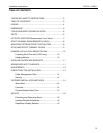
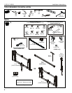
HANGING LVS1U/LVSXU MOUNT ON RAIL
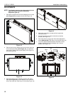
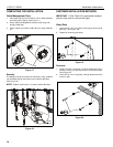
Preparing Strut Channel (LVSXU only)
1. On the top rail, slide one inner stop clamp (S) into end of
strut channel section. (See Figure 6)
2. Fasten outer stop clamp (R) to inner stop clamp (S) using
one 1/4-20 x 1/2" hex head screw (T). (See Figure 6)
3. Repeat for each end of each top section of strut channel.
Figure 6
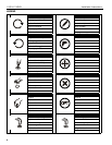
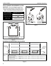
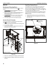
Hanging Mounts
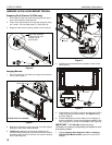
1. Lift mount and hang it on lower lip of upper strut channel or
rail (V). (See Figure 7)
Figure 7
2. Repeat for remaining mounts in that row, and slide mounts
along strut channels to desired location.
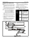
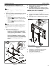
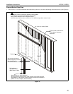
3. LVSXU only: Add lower strut channel to bottom of all
mounts in row by lifting strut channel up from below mounts
and setting upper lip of strut channel onto mounts’ latching
hooks. (See Figure 8)
Figure 8
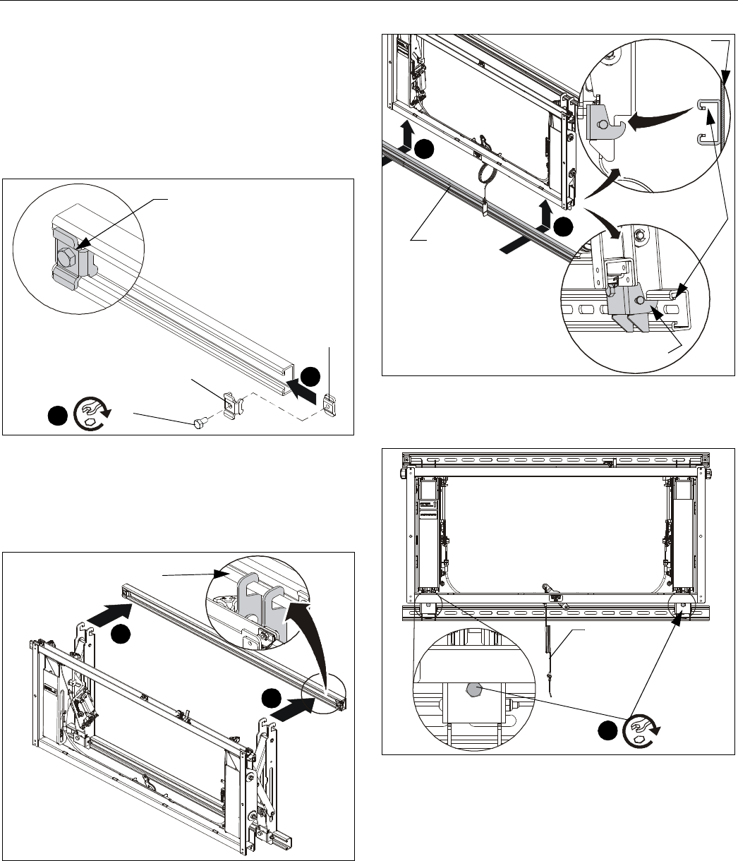
4. Tighten two hex head fasteners at bottom of each mount.
(See Figure 8)
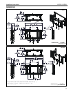
Figure 9
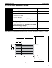
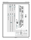
5. Fasten bottom rail (LVS1U) or lower strut channel (LVSXU)
to wall using the provided hardware. See Parts drawing,
and (See Table 2).
6. Extend RapidDraw pull cord to bottom row of displays so
that it is accessible, re-tie to correct length and label the pull
cord using label (Y) so that it is identifiable. (See Figure 9)
IMPORTANT ! : See Service section for more
information on properly configurating the RapidDraw cord
and display release.
7. Repeat Attaching Strut Channel or Rail and Hanging
LVS1U/LVSXU Mount On Rail sections for each row of
displays.
(R)
(S)
1
2
(T)
Stop clamp fastened
in place at each end
of upper row of
strut channel
(LVS1U shown as example)
1
1
lower lip of strut
channel or rail
3
3
side
view
mount hooks
strut channel
upper lip
lower strut
channel
wall
5
x 2
RapidDraw
pull cord