LVS1U / LVSXU Installation Instructions
12
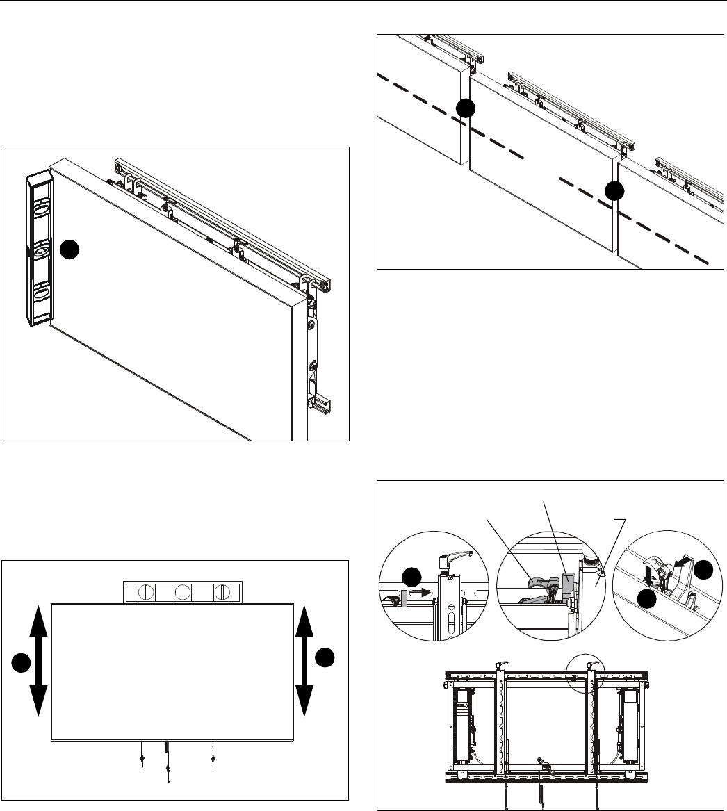
ADJUSTMENTS
NOTE: The following steps are also referenced on the next
page (See Figure 16) and the PowerZone
Adjustment guide (Z).
1. Place the level against the front of the display and use knob
(#1 in Figure 16) to straighten the tilt. (See Figure 12)
Figure 12
2. Place a level on top of display and use the knobs at the top
of the interface brackets (#2 in Figure 16), to raise/lower
each side of display and level the display. (See Figure 13)
and (See Figure 16)
Figure 13
3. Place level across face of adjoining screens and adjust
depth (#3 in Figure 16) to make displays flush across the
front of the video wall. (See Figure 14) and (See Figure 16)
Figure 14
4. Slide latch mechanism until tab sits flush against the
interface bracket.
5. Pull tab forward to lock latch mechanism to interface
bracket. (See Figure 15)
6. Push latch down to engage the micro lateral adjustment
knobs (#4B and #4C). (See Figure 15) and (See Figure 16)
7. Turn micro lateral adjustment knobs clockwise to move
display toward knob end until displays are in correct
position. (See Figure 16)
Figure 15
1
2
2
3
3
(Display not shown)
6
5
4
Tab
Latch
Interface
bracket


