


LVS1U / LVSXU Installation Instructions
14
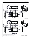
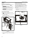
COMPLETING THE INSTALLATION
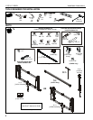
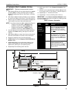
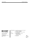
Cable Management Clips
1. Place cable clip (Q) into rail and turn 90° in either direction
until cable clip is vertical. (See Figure 17)
2. Route cables and RapidDraw release cords along rails,
through cable clips.
3. Fasten cables and cords to cable clips (Q) using cable ties
(P).
Figure 17
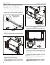
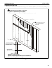
Security
The displays may be secured to the mounts by using a padlock
(not included) through the bottom of the interface brackets.
(See Figure 18)
NOTE: Padlock must have a 1/4" (6mm) shackle diameter.
Figure 18
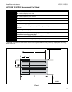
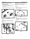
FASTENER INSTALLATION METHODS
IMPORTANT ! : (See Table 2) for appropriate hardware
and pilot hole sizes for various wall types.
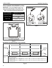
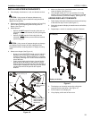
Wood Stud
1. Use one 5/16" x 2-1/2" lag bolt (L) through product and into
pilot hole. (See Figure 19)
2. Repeat for remaining pilot holes.
Figure 19
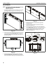
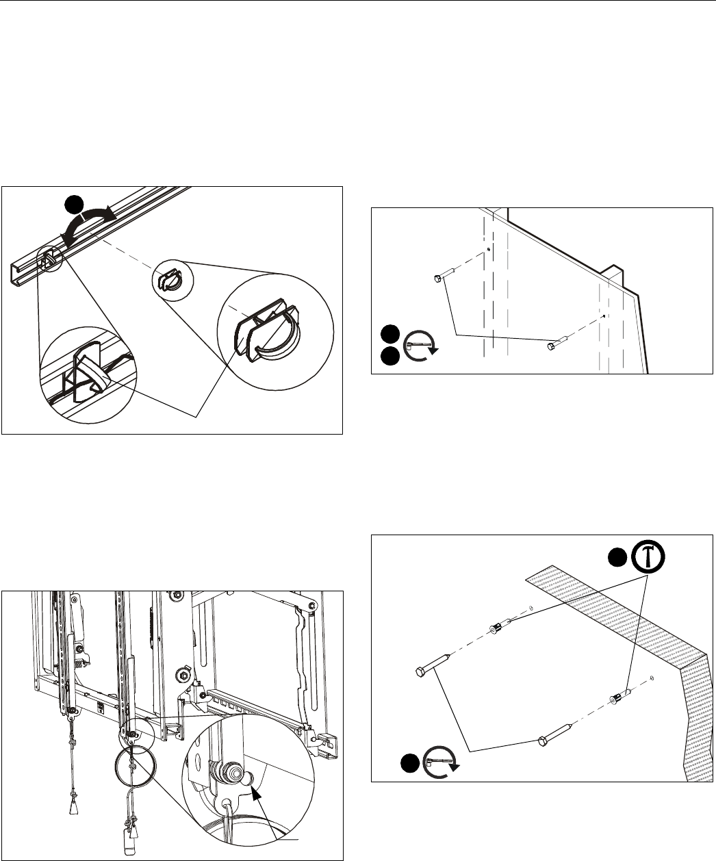
Concrete
1. Install one UX10 x 60 anchor (J) into each pilot hole using a
hammer, making sure that the anchor is flush with the wall.
(See Figure 20)
2. Use one 5/16" x 2-1/2" lag bolt (L) through product into each
anchor in wall.
Figure 20
1
(Q)
Insert
padlock
1
2
(L) x 2
1
2
(L)
(J)