


Installation Instructions LVS1U / LVSXU
9
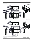
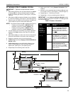
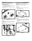
ATTACHING STRUT CHANNEL OR RAIL
IMPORTANT ! : Reference measurements noted on
page 7.
1. Mark distance (F) from floor to desired location for bottom
of display OR from ceiling to desired location for top of
display (if installing top row first). (See Figure 1) and (See
Figure 5)
2. Mark distance (G) from bottom of display (or top of display)
to center line of display. (See Figure 1) and (See Figure 5)
3. Measure up 8-3/4" (222mm) from centerline of display and
mark location for top strut channel/rail attachment.
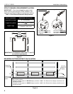
NOTE: If an offset measurement (H) is needed (See Figure 4):
• If display mounting pattern is BELOW display
centerline, measure up: 8-3/4" (222mm) - H
• If display mounting pattern is ABOVE display
centerline, measure up: 8-3/4" (222mm) + H
4. Level and attach strut channel/rail (V) using the provided
hardware. See Parts drawing, (See Figure 5) and (See
Table 2).
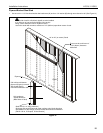
5. Mark distance (D) (up or down) from first strut channel/rail
slots and mark location of next row of strut channel/rail.
6. Repeat for remaining rows of strut channels/rails.
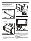
7. (LVSXU only) Proceed to Hanging LVS1U/LVSXU Mount
On Rail section.
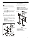
8. (LVS1U only) Measure over (C) (width of display) from
center of first installed rail, level and mark location of
adjacent rail. (See Figure 1) and (See Figure 5)
9. Repeat Step 8 for remaining rails in that row.
10. Attach upper rails (V) using Fastener Information. (See
Table 2)
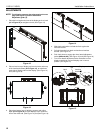
11. Measure up from attached rails the distance (D) and mark
for next row of rails (V). (See Figure 1) and (See Figure 5)
12. Repeat Steps 4 - 10 for that row of rails.
13. Repeat Step 11 for any remaining rows of rails (V).
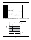
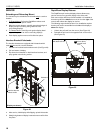
IMPORTANT ! : See Fastener Installation Methods section
at end of Installation Instructions for details on installing product
into various wall types.
Table 2: Fastener Information
WALL
TYPE
PILOT
HOLE
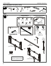
FASTENERS (see PARTS
drawing)
Drywall
attached to
plywood-
backed walls
/Steel studs
N/A #14 x 1-1/2" hex slot head screw
(N) & 1/4" washer (M). Fasteners
placed a maximum of 8" (203mm)
apart AND
in last slots on each end of
strut channel.
Wood stud
(2" x 4")
7/32" x 3"
5/16 x 2-1/2" hex head lag (L) &
5/16" washer (K). Fasteners placed
at stud locations, min. 16" (400mm)
and max. 24" (610mm) AND within 9"
(230mm) of each end of the rail/strut
channel.
Concrete
3/8" x 3" 5/16 x 2-1/2" hex head lag (L) &
Fischer UX10x60 anchor (J).
Fasteners placed a min. 16" (400mm)
and max. 24" (610mm) apart AND
within 9" (230mm) of each end of the
rail/strut channel.
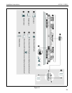
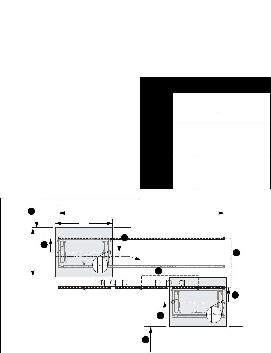
Figure 5
Top rail - LVS1U
Top strut channel - LVSXU
Ceiling
Centerline - display
Centerline - display
C
I
D
1
2
3
Floor
1
2
3
5
7
H
C
D