


Model MSP-DCCMD Installation Instructions
10
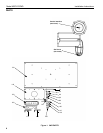
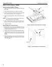
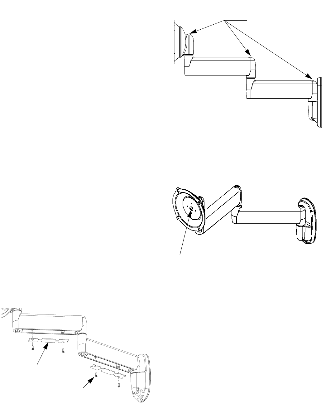
CABLE MANAGEMENT
WARNING: Make sure your cables do not run through
a pinch point.
1. Connect and secure power/audio/video cables,
making sure to leave sufficient slack to allow for
movement of the display.
2. Route power/audio/video cables under each arm,
allowing sufficient slack in cables for extension and
avoiding pinch points.
3. Secure cables using two cover plates (160) and four
screws (90). (see figure 11)
ADJUSTMENTS
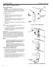
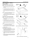
LATERAL TENSION ADJUSTMENT
CAUTION: Overtightening adjustment will cause
excessive wear.
1. Using a 3/16” hex wrench (170), slightly tighten or
loosen lateral tension adjustment bolts.
(see figure 12)
2. Check for desired tension.
3. Repeat Steps 1 and 2 until desired tension is
obtained.
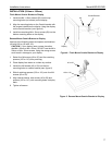
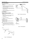
PITCH ADJUSTMENT
CAUTION: Overtightening adjustment screw will
cause excessive wear.
NOTE: Remove display to make pitch adjustment.
1. Check adjustment screw on the Centris interface to
ensure that the screw is tight. (see figure 13)
2. If needed, use a 3/16” hex wrench (170) to tighten the
screw.
Figure 11: Cable Management
Figure 12: Adjust Lateral Tension
Figure 13: Pitch Adjustment
90
160
Lateral Tension
Adjustment Bolts
Pitch Tension
Adjustment Screw