


Installation Instructions Model MSP-DCCMD
5
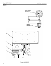
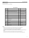
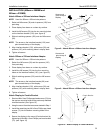
PARTS (Continued)
Table 2 below provides a list of the JWD parts.
NOTES:
‡The M4 x 12mm screws (60) are used on the Centris interface for flush mount applications.
*The M4 x 30mm screws (40) with spacers (100) are for recessed mount applications.
**M4 x 20mm screws (50) with spacers (110) are for recessed mount applications.
***The six M4 x 16mm screws (80) and six spacers (190) are used to attach the interface adapter (140) to the
display.
£The M6 x 20mm screws (30) are used with spacers (120) and the interface adapter (130).
‡The M4 x 8mm screws (70) are also used to attach the Centris interface to the interface adapter (140).
Table 2: JWD Parts
ITEM
NUMBER
DESCRIPTION QTY USED WITH NOTES
10 JWD MOUNT 1
20 3/8” x 3” LAG SCREWS 2 USE WITH 150
30 PHILLIPS PAN HEAD MACHINE SCREW, M6 x 20mm 6 USE WITH 110 AND 120£
40 PHILLIPS PAN HEAD MACHINE SCREW, M4 x 30mm 4 USE WITH 100*
50 PHILLIPS PAN HEAD MACHINE SCREW, M4 x 20mm 4 USE WITH 110**
60 PHILLIPS PAN HEAD MACHINE SCREW, M4 x 12mm 4 USE WITH
CENTRIS INTERFACE‡
70 PHILLIPS PAN HEAD MACHINE SCREW, M4 x 8mm 4 USE WITH 140
80 PHILLIPS FLAT HEAD MACHINE SCREW, M4 x 16mm 6 USE WITH 140***
90 PHILLIPS FLAT HEAD MACHINE SCREW, 8-32 x 3/8” 4 USE WITH 160
100 3/4” THICK NYLON SPACER 4 USE WITH 40*
110 3/8” THICK NYLON SPACER 4 USE WITH 50**
120 5/16” THICK NYLON RETAINING SPACER
(.75 Outside Diameter)
6 USE WITH 30
130 INTERFACE ADAPTER (400mm x 200mm and
550mm x 235mm
1 USE WITH 30 AND 120
140 200mm x 100mm INTERFACE ADAPTER 1 USE WITH 70 AND 80
150 WALL BRACKET 1 USE WITH 20
160 COVER PLATE 2 USE WITH 90
170 3/16” HEX KEY 1 FOR JOINTS
180 5/32” HEX KEY 1 FOR SET SCREW
190 1/8” NYLON SPACER 6 USE WITH 80