


Stand-alone DVR Instruction Manual
24
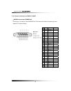
5-4. Installation
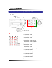
5-4.1. Camera Connection
▫ Connection of Normal Cameras
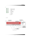
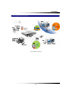
Connect the cameras to the Video Input (BNC connector) on the back of the unit as shown
above [Fig. 5-3 System Connection].
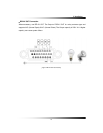
▫ Connection of Loop Output
The Camera or video output is available from the Video Output (Loop Output) on the back of
the unit. (When BNC jack is connected to the Video Output, the termination resistance (75Ω)
is automatically switched to impedance status so the external device must have termination
resistance.)
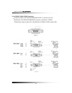
5-4.2. Monitor Connection
▫ Connection of Main Monitor
Connect the composite monitor to "Main" on the upper part of BNC connector
▫ Connection of Auxiliary Monitor
Connect the auxiliary monitor to "Aux" on the lower part of BNC connector. The output of
auxiliary monitor port is the same as the main monitor.