


- 44 -
Service manual WP 895/895F, CP885/885F
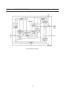
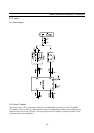
5-2-5 Video Demodulation and Amplifier
The video IF signal, which is applied from the gain controlled IF amplifier, is multiplied with the in-phase component
of the VCO signal. The video demodulator is designed for low distortion and large bandwidth. The demodulator output
signal passes an integrated low pass filter for attenuation of the residual vision carrier and is fed to the video amplifier.
The video amplifier is realised by an operational amplifier with internal feedback and 8 MHz bandwidth (–3 dB). A
standard dependent dc level shift in this stage delivers the same sync. level for positive and negative modulation. An
additional noise clipping is provided. The video signal is fed to VIF-AGC and to the video output buffer. This amplifier
with a 6 dB gain offers easy adaptation of the sound trap. For nominal video IF modulation the video output signal at
Pin 12 is 2 Vpp.
5-2-6 Sound IF Amplifier and SIF-AGC
The SIF amplifier is nearly identical with the 3-stage VIF amplifier. Only the first amplifier stage exists twice and is
switchable by a control voltage at Pin 3. Therefore with minimal external expense it is possible to switch between two
different SAW filters. Both SIF inputs features excellent cross-talk attenuation and an input impedance which is
independent from the switching condition. The SIF-AGC is related to the average level of AM- or FM-carrier and
controls the SIF amplifier to provide a constant SIF signal to the AM demodulator and QPS mixer.
5-2-7 Quasi-Parallel-Sound (QPS) Mixer
The QPS mixer is realised by a multiplier. The SIF signal (FM or NICAM carrier) is converted to the intercarrier
frequency by the regenerated picture carrier (quadrature signal) which is provided from the VCO. The intercarrier
signal is fed via an output amplifier to Pin 24.
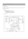
5-2-8 Standard Switch
To have equal polarity of the video output signal the polarity can be switched in the demodulation stage in accordance
with the TV standard. Additionally a standard dependent dc level shift in the video amplifier delivers the same sync. level.
In parallel to this, the correct VIF-AGC is selected for positive or negative modulated VIF signals. In the case of
negative modulation (e.g., B/G standard) the AM output signal is switched off. For positive modulation (L standard) the
AM demodulator and QPS mixer is active. This condition allows a parallel operation of the AM sound signal and the
NICAM-L stereo sound.
5-2-9 L’ Switch
With a control voltage at Pin 14 the VCO frequency can be switched for setting to the required L’ value (L’ standard).
Also a fine adjustment of the L’-VCO center frequency is possible via a potentiometer. The L’ switch is only active for
positive modulated video IF-signals (standard switch in L mode).
5-2-10 Internal Voltage Stabiliser
The internal bandgap reference ensures constant performance independent of supply voltage and temperature.