


- 64 -
Service manual WP 895/895F, CP885/885F
*
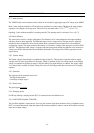
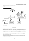
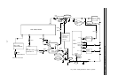
power supply functioning during TV set normal run mode
- I801 transmits controlled pulses to T801 which generates DC voltages after rectifications by secondary part diodes
and electro capacitors (by example by D820 and C813 on 143V supply voltage line).
- 8V, 5V, 3.3V supply voltage lines have stabilized voltages obtained by I820, I822, I823 voltage regulators.
- On 143V supply voltage line, R823 resistor has been chosen to reach exact DC voltage required on this line.
- 143V supply voltage line includes an IC error amplifier (I806) which corrects unexpected DC voltage variations on
this line.
*
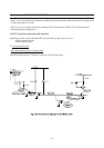
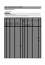
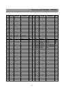
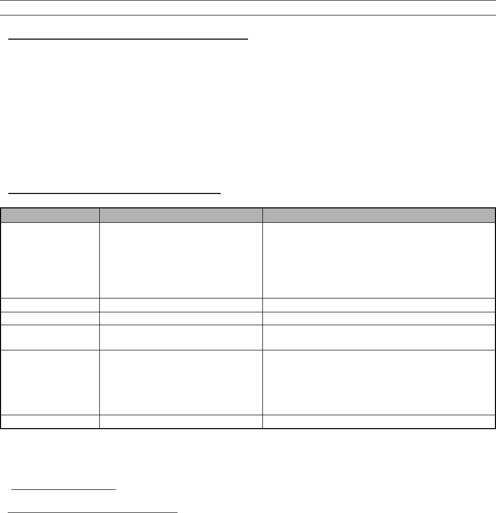
power supply IC delivery during TV set normal run
power supply line IC power supply delivery Remarks
143V FBT FBT supplies 43V to I301 vertical IC
FBT supplies 43
V to T401 H- drive for CP785
FBT supplies 12V to I301 vertical IC
FBT supplies 33V to the tuner
FBT supplies 188V to I901 video amplifier pin 6
14.5V I602 sound amplifier pins 3-16
14V T401 H- drive
8V I501 Main IC pins 14-39
I601 Sound Demod pins 38-39-40
5V I703 IR receiver pin 1
I501 Main IC pins 3-15-45
I601 Sound Demod pins 7-18-57
I702 EEPROM pin 8
tuner
3.3V I501 Main IC pins 25-54
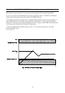
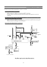
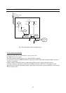
b) TV set on stand-by mode
*
TV set circuit diagram on stand-by mode