


- 66 -
Service manual WP 895/895F, CP885/885F
I810
CONTROLLED
RECTIFIER
R820
R830
C830
R829
Q
808
6V DC
Q
809
Q
807
HIGH
HIGH
HIGH
LOW
POWER
LOW
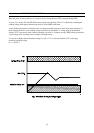
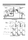
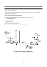
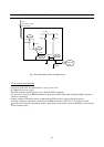
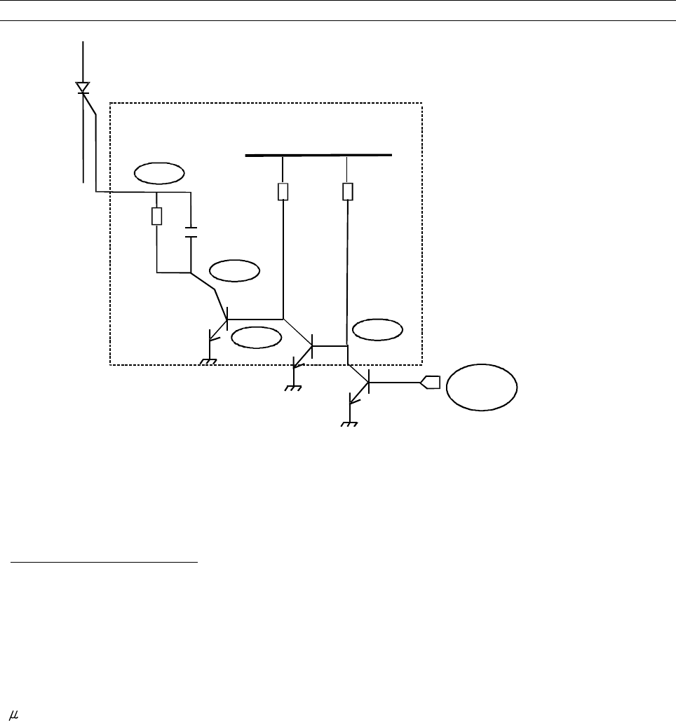
Fig : I810 controlled rectifier switching circuit
* TV set stand-by mode operations
- On stand-by mode, I501 microcontroller pin 1 (power) is set to low.
- So, Q809 collector is set to high.
- Then, I810 controlled rectifier gate pin is set to high and I810 is conducting.
- So, current flows from pin 16 SMPS transformer to the ground via I804 optocoupler and Q810 and Q811 transistors
(which are conducting).
- In these conditions, I801 delivers pulses on light mode and T801 produces voltages with reduced power.
- As I810 is conducting, current flows also from pin 16 SMPS transformer to I823 (5V / 3.3V regulator) for I501
com, IR receiver and front mask buttons supply voltage (then, remote control or front mask buttons can be activated
to leave stand-by mode).