


- 63 -
Service manual WP 895/895F, CP885/885F
On normal run mode, I501 microcontroller pin 1 (power) is set to high
•
So, I810 controlled rectifier is not conducting
- Q809 is conducting. So, Q808 is not conducting and Q807 is conducting
- So, Q807 collector is connected to the ground and I810 controlled rectifier gate pin is set to low (no
conducting)
•
So, current from 14V DC voltage (from T801 SMPS transformer pin 13) does not flow through Q811 and Q810
transistors but flows through I806 IC error amplifier
- Q809 is conducting. So, Q810 is not conducting and no current flows from Q810 collector to the ground
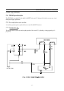
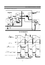
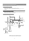
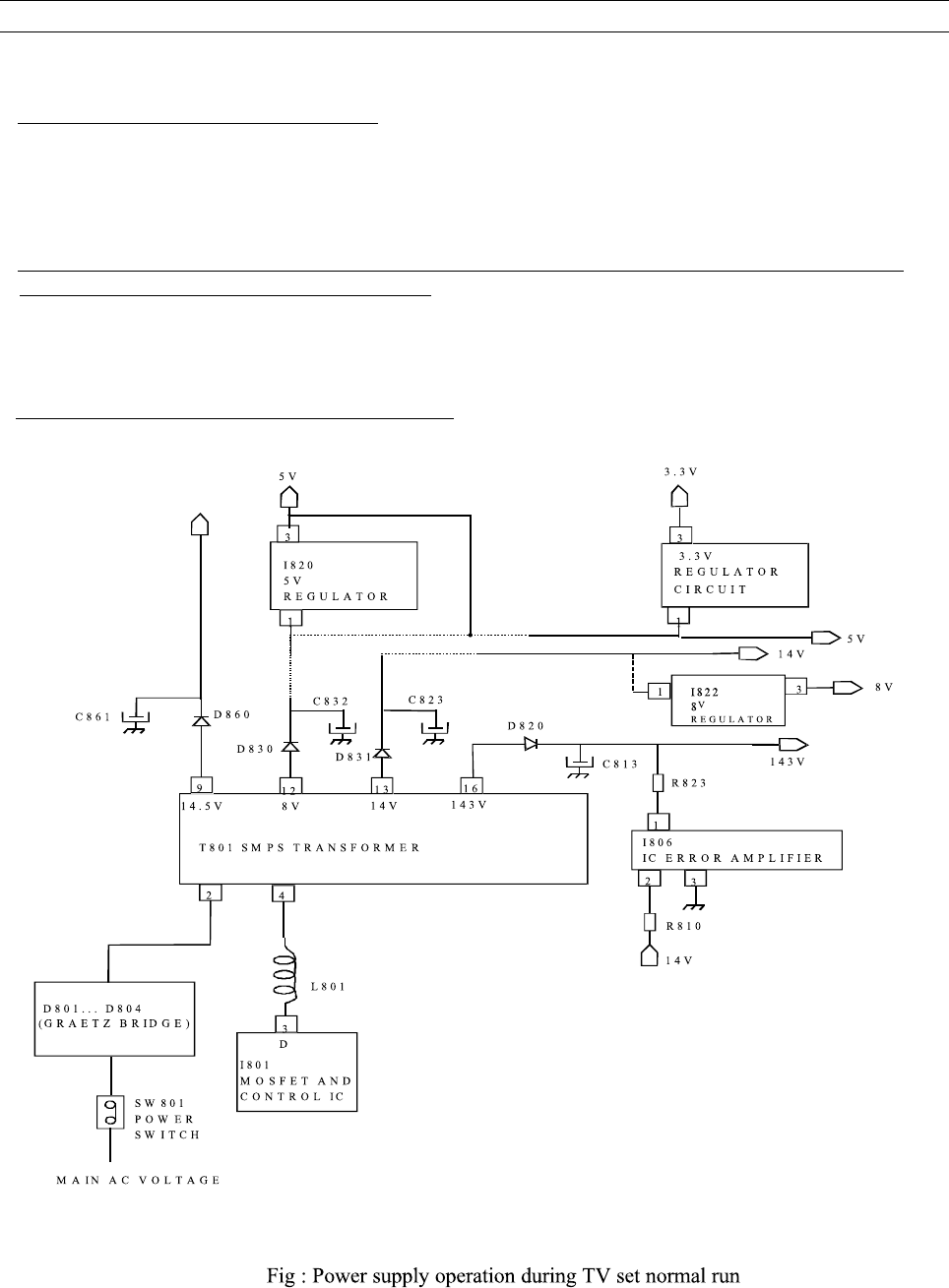
Therefore, the power circuit diagram is the following one :
*
power supply circuit diagram during TV set normal run