


- 58 -
Service manual WP 895/895F, CP885/885F
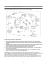
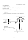
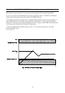
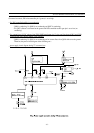
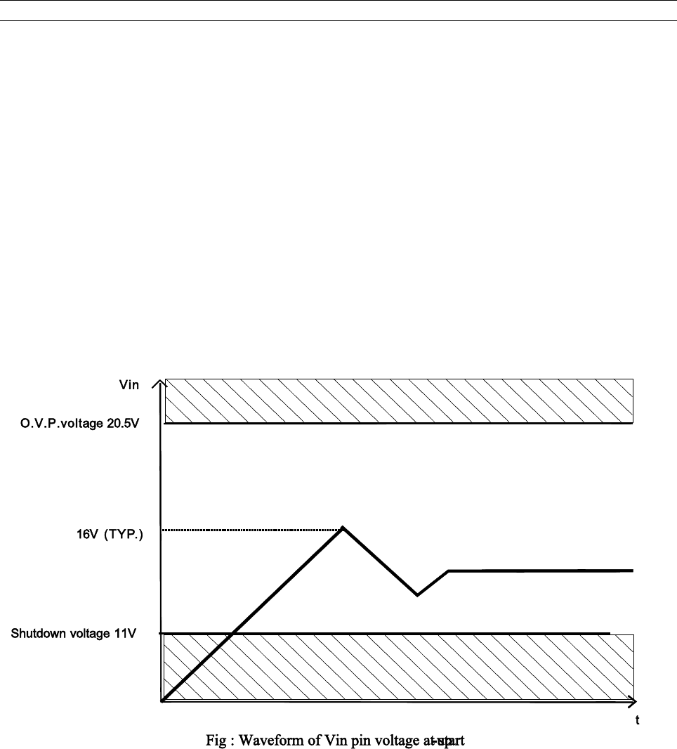
When the power switch is pushed on, V
IN
increases slowly. During this time, C806 is charged through R802.
As soon as V
IN
reaches 16V, the STR-F6654 control circuit starts operating. Then, V
IN
is obtained by smoothing the
winding voltage which appears between pin6 and pin7 of the SMPS transformer.
As this winding voltage does not increase to the set voltage immediately after the control circuit starts operating, V
IN
starts dropping. However, as this winding voltage reaches the set value before V
IN
voltage drops to the shutdown
voltage (at 11V), the control circuit continues operating (see below V
IN
voltage at start-up). R805 resistor prevents that
V
IN
pin voltage varies according to the secondary side output current.
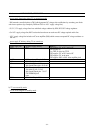
V
IN
must be set higher than the shutdown voltage (V
IN
(off) = 11V
max
) and lower than the O.V.P. (overvoltage
protection) operating voltage
(V
OVP
= 20.5V
min
)