


11
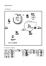
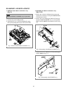
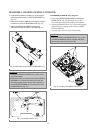
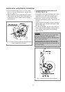
d. Separate the LOADING LEVER Ass’y by pressing the
connection point from the CASSETTE HOLDER Ass’y.
(Fig. 3.4)
e. Remove the SAFETY SPRING connecting the SAFETY
LEVER and CASSTTE HOLDER PLATE. (Fig. 3.4)
f. Remove the RELEASE SPRING connecting the
RELEASE LEVER and SAFETY LEVER. (Fig. 3.4)
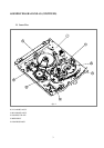
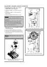
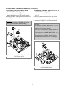
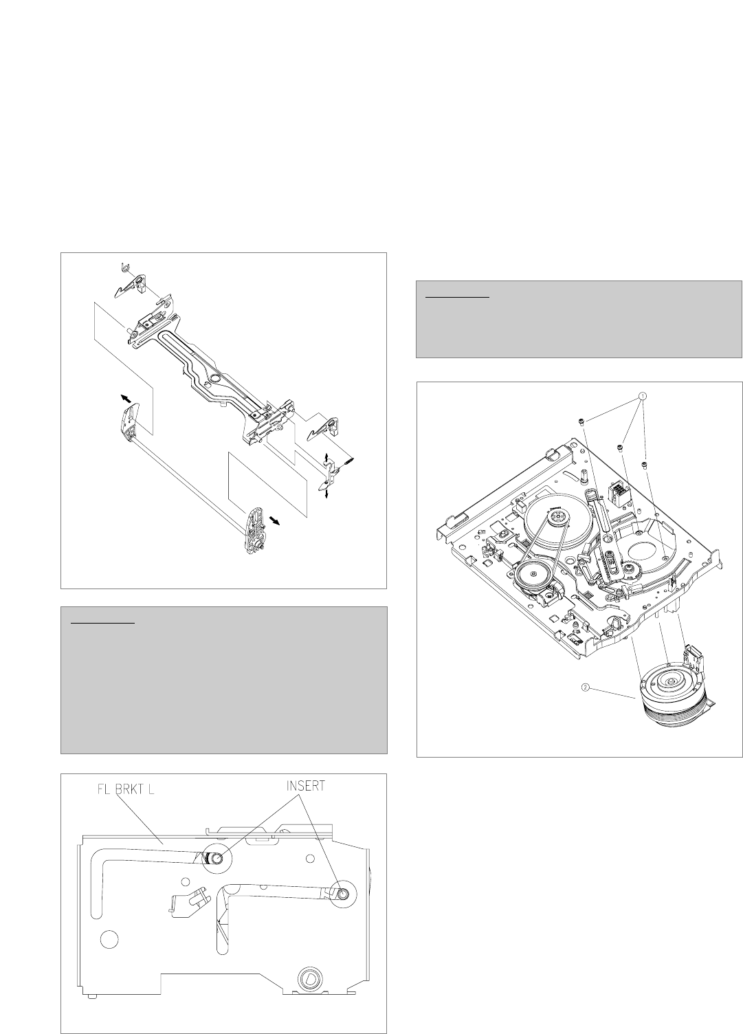
3. Deassembly of DRUM Ass’y (Fig. 3.6)
a. Turn over the DECK MECHANISM and holding the
DRUM TOTAL Ass’y @ with hands, remove the 3
screw holding the drum total assembly with mainbase.
b. Separate the DRUM TOTAL Ass’y from the deck paying
attention there is no damage on the surface of VIDEO
HEAD and DRUM.
c. Assembly step is the reverse way of deassembly.
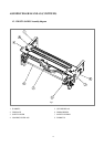
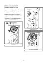
DEASSEMBLY AND REPLACEMENT (CONTINUED)
CAUTION:
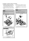
• Assemble the FRONT LOADING Ass’y in the reverse
step of deassembly.
• Confirm that 2 bosses on the left side of the CASSETTE
HOLDER Ass’y are inserted in the groove on the left
side of the top plate. Insert 2 bosses on the right side of
the CASSETTE HOLDER Ass’y into the groove of the
F/L BRACKET R. (Fig. 3.5)
FIg. 3.4 Deassembly of the CASSETTE HOLDER Ass’y
FIg. 3.5 Assembly of the FL Ass’y
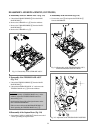
CAUTION:
• After the assembly of the DRUM TOTAL Ass’y, check
out if DECK Mechanism operate smoothly and adjust-
ment of tape transmission section is OK.
FIg. 3.6 Assembly of the DRUM TOTAL Ass’y