


13
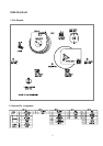
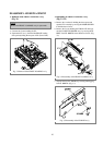
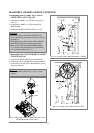
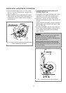
6. Deassembly of the LC BRKT ASS’Y, PINCH
LEVER TOTAL ASS’Y (Fig. 3.10)
a. Separate the LC BRKT Ass’y @ after removing the 3
screw !.
b. Separate the LC BRKT Ass’y @ from the DECK
MECHANISM.
c. Disintegrate the PINCH LEVER TOTAL Ass’y #.
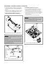
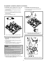
7. Deassembly of the CAM GEAR, RELAY LEVER,
FL RACK (Fig. 3.10)
a. Separate the CAM GEAR % from the MAINBASE.
b. Separate the RELAY LEVER ^ from the MAINBASE.
c. Separate the FL RACK & from MAINBASE by moving
to the arrow direction.
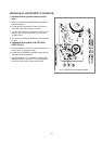
DEASSEMBLY AND REPLACEMENT (CONTINUED)
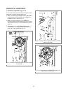
CAUTION:
• After the assembly of the PINCH LEVER TOTAL
Ass’y, adjust the tape transmission section by refering to
the chapter 5.
• There should be no pollution on the surface of PINCH
ROLLER $ with grease or other foreign material.
• Make sure if the end of the PINCH SPRING PINCH
“A” is located at the end of trajectory of CAM GEAR
“B” in assembly. (Refer to Fig. 4.3)
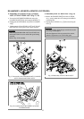
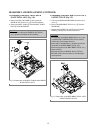
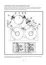
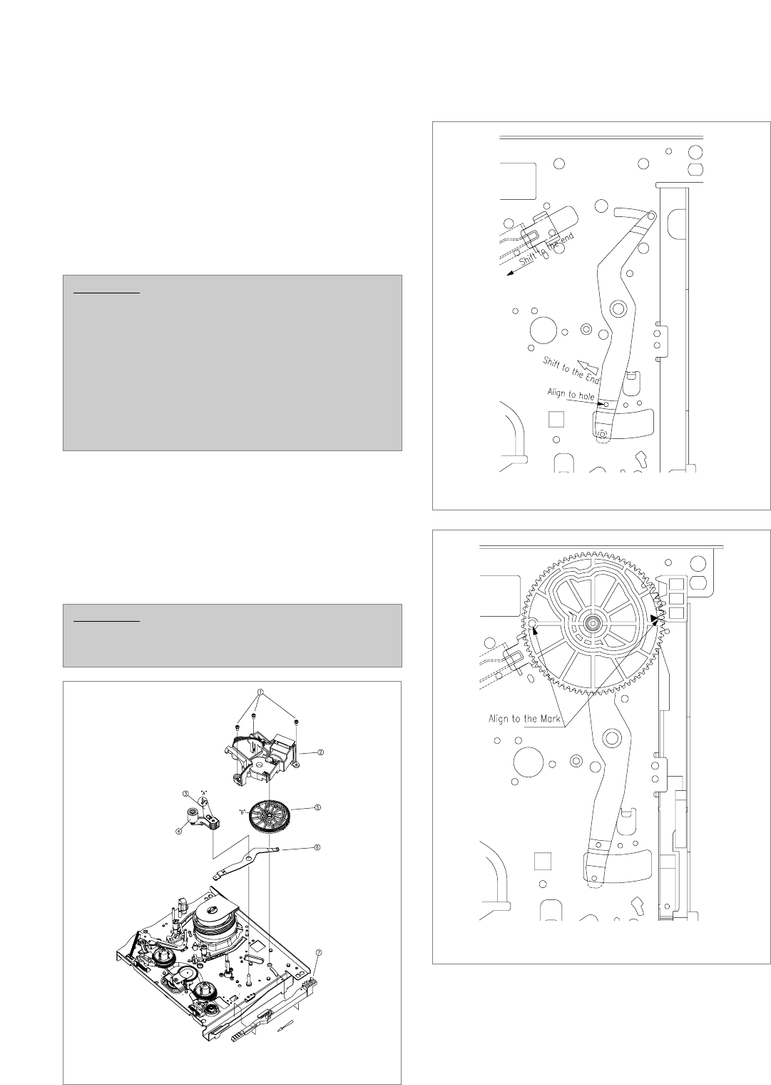
CAUTION:
• When reassembling, refer to Fig. 3.11, Fig. 3.12 and
chapter 4.
FIg. 3.10 Deassembly of the LC BRACKET ASS’Y from
the PINCH LEVER TOTAL ASS’Y
FIg. 3.11 Assembly of the CAM GEAR, RELAY LEVER
FIg. 3.12 Assembly of the CAM GEAR, FL RACK