


14
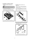
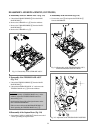
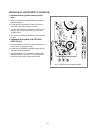
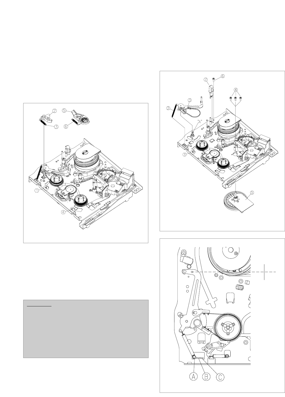
8. Deassembly of the S/T BRAKE ASS’Y (Fig. 3.13)
a. Unhook the S BRAKE SPRING # from the MAIN-
BASE HOOK !.
b. Remove the S BRAKE Ass’y @ from the mainbase.
c. Remove the T BRAKE SPRING ^ from the MAIN-
BASE HOOK $.
d. Remove the T BRAKE Ass’y %.
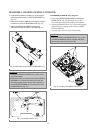
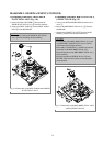
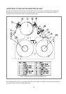
9. Deassembly of the TENSION BAND ASS’Y
(Fig. 3.14)
a. Unhook the TENSION SPRING @ from the MAIN-
BASE HOOK !.
b. Unhook the MAINBASE HOOK “A” and remove the
TENSION BAND Ass’y # from the mainbase.
10.Deassembly of the Capstan Motor (Fig. 3.14)
a. Separate the CAPSTAN MOTOR % after the removal of
3 screw $ holding the capstan motor.
11. Deassembly of the FE HEAD (Fig. 3.14)
a. Unscrew the screw ^ and separate the FE HEAD &
from the MAINBASE.
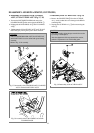
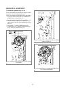
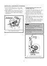
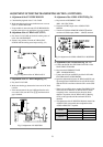
DEASSEMBLY AND REPLACEMENT (CONTINUED)
CAUTION:
• After the assembly of TENSION BAND Ass’y on the
mainbase, adjust the TENSION POLE location as
shown in Fig. 3.15.
• Avoid getting Grease, Oil or Foreign substance on the
FELT of the BAND BRAKE.
• Take care not to deform the MAINBASE HOOK “A”
when separating the TENSION BAND Ass’y #.
FIg. 3.13 Deassembly of the S/T BRAKE ASS’Y
FIg. 3.14 Deassembly of the TENSION BAND ASS’Y,
CAPSTAN MOTOR and the FE HEAD
FIg. 3.15 Adjustment of the TENSION POLE POSITION