


17
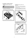
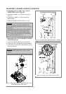
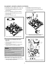
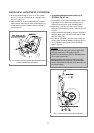
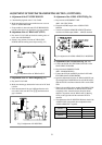
d. Make sure that the triangular mark “A” of the L LOAD-
ING Ass’y is aligned with the mark “b” of the R LOAD-
ING Ass’y. (Fig. 4.4)
e. Reference hole “C” of the LOADING RACK should be
aligned with the reference hole of the R LOADING Ass’y
to make the teeth of the LOADING RACK is aligned as
shown in Fig. 4.4.
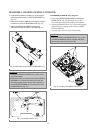
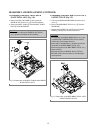
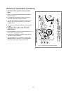
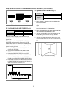
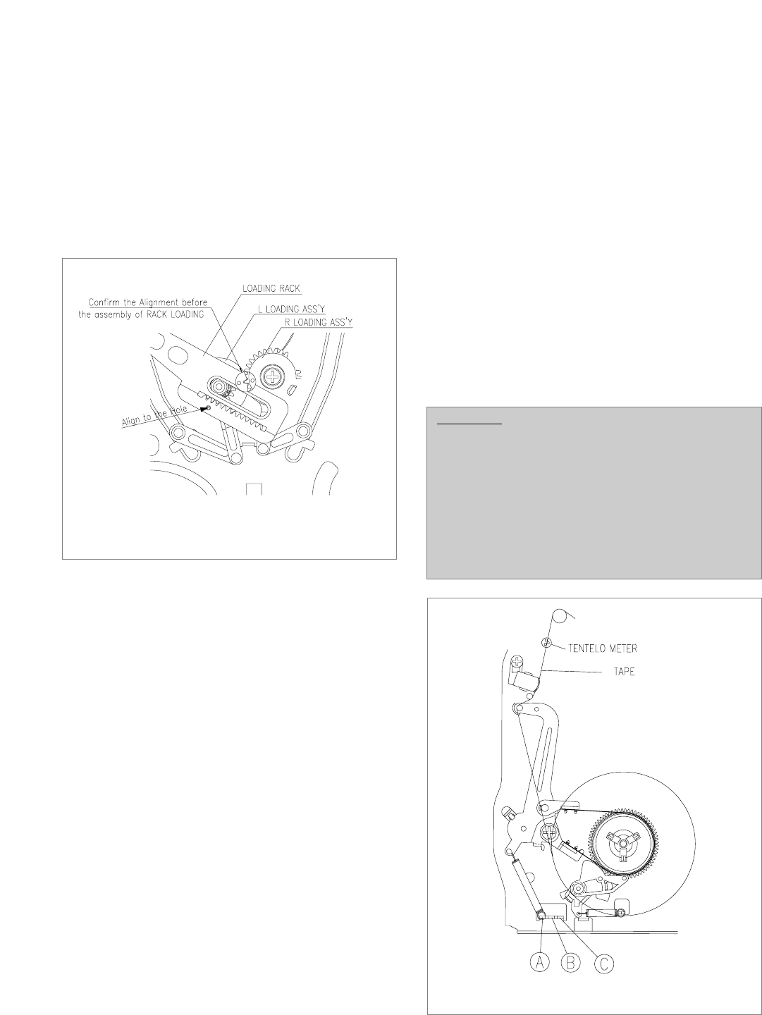
2. Adjustment and measurement of the BACK
TENSION (Fig. 4.5, 4.6)
a. Check that the location of the TENSION POLE is in the
right position. If not, adjust that by refering to the “4.
Adjustment of the position of the TENSION POLE”.
b. Playback the T-120 Tape in S-MAX for 20 seconds.
(Generally tape transporting section is settled down in 20
seconds)
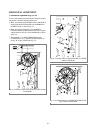
c. Measure the BACK TENSION by using the TENTELO
METER. (Refer to Fig. 4.5) The result should be within
the range of 20g~30g.
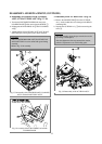
d. If the BACK TENSION is out of the range, change the
position of the TENSION SPRING of repeat the process
of “4. Adjustment of the position of the TENSION
POLE”. (Fig. 4.6)
MECHANICAL ADJUSTMENT (CONTINUED)
FIg. 4.4 Assembly reference between the LOADING RACK
and the LOADING LEVER ASS’Y
CAUTION:
• If the measurement result greater than the upper limit,
change the hook point of the spring to the “A”.
• Confirm that all of the three probes of TENSION meter
are in contact with the tape.
• During measuring, don’t touch any other parts of the
MECHANISM(i.e, MAINBASE). It is recommended
that this measurement be repeated at least three times for
an accurate reading.
FIg. 4.5 Measurement of the BACK TENSION