


22
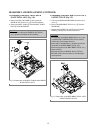
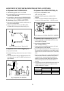
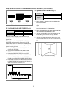
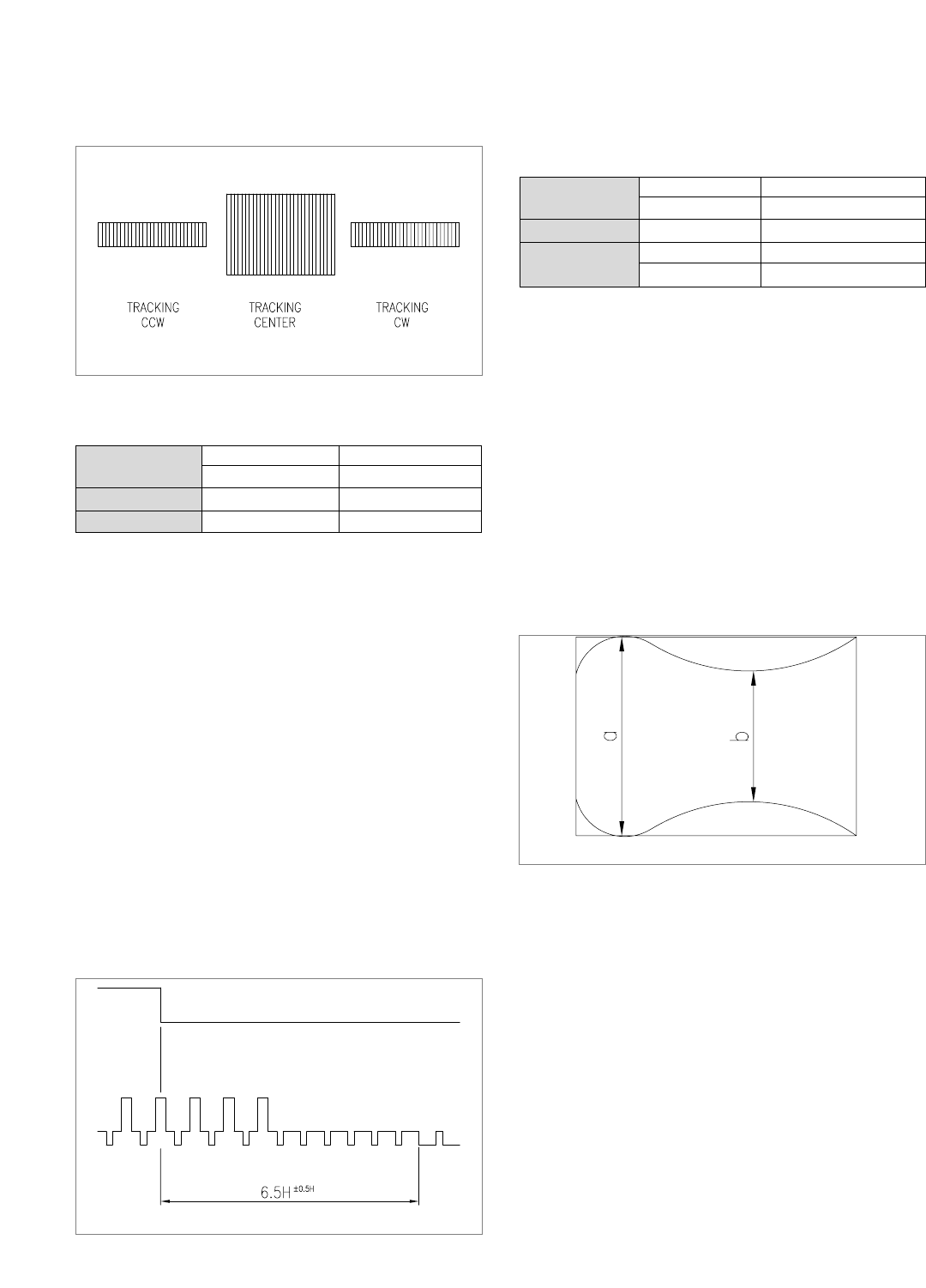
F. PLAYBACK PHASE ADJUSTMENT(Fig. 5.6)
PHASE GENERATOR(PG) SHIFTER determine the
VIDEO HEAD SWITCHING POINT when the TAPE is
played back.
If an adjustment of the PHASE GENERATOR(PG)
SHIFTER is not doneprecisely, There can be a HEAD
SWITCHING NOISE or a VERTICAL JITTER problem,
vibration of the picture on the screen, not good quality of
picture in special play back.
a. Connect the PT01 on the MAIN CIRCUIT BOARD with
a PATH ADJ. FIXTURE.
b. Play back an ALIGNMENT TAPE (DN-2 : MON-
SCOPE).
c. Connect the S/W PULSE TEST PIN on the PATH
ADJ.FIXTURE with a CHANNEL-1 SCOPE PROBE.
d. Connect the VIDEO OUT on the MAIN CIRCUIT
BOARD with a CHANNEL-2 SCOPE PROBE(1V/div).
e. Control thePG VOLUME until the time interval between
the SWITCHING PULSE and the V-SYNC SIGNAL is
sithin the 6.5±0.5H as shown in fig. 5.6
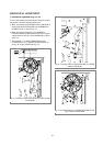
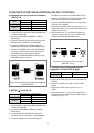
G.Adjustment of the LINEARITY(Fig. 5.7)
a. Connect the PT01 on the MAIN CIRCUIT BOARD with a
PATH ADJ.FIXTURE.
b. Play back an ALIGNMENT TAPE (DN-2 : MONOSCOPE
Signal).
c. Connect the FIXTURE S/W PULSE TEST PIN on the
PATH ADJ. CHANNEL-1 SCOPE PROBE.
d. Connect the VIDEO OUT on the MAIN CIRCUIT BOARD
with a CHANNEL-2 SCOPE PROBE.(1V/div).
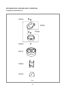
e. Adjust the VR CONTROL on the ADJ. FIXTURE until the
ENVELOPE signal is maximum while play back the
ALIGNMENET TAPE.
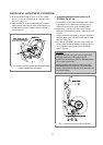
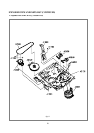
f. Adjust the S/T GUIDE ROLLER until the envelope signal
waveforms of the entrance and exit sides are as shown in Fig.
5-7.
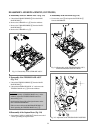
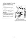
ADJUSTMENT OF THE TPAE TRANSPORTING SECTION. (CONTINUED)
FIg.5.5 Adjustment of the X-POSITION
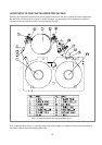
S/W PULSE TEST PIN MAIN CIRCUTE BOARD
ENVELOPE TEST PIN MAIN CIRCUTE BOARD
Measurement Equipment OSILLOSCOPE
VR 595(PG SHIFTER) MAIN CIRCUTE BOARD
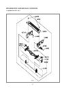
Test Point
S/W PULSE TEST PIN PATH ADJ. FIXTURE
ENVELOPE TEST PIN PATH ADJ.FIXTURE
Measurement Equipment OSILLOSCOPE
VR CONTROL PATH ADJ.FIXTURE
S/T GHIDE ROLLER TAPE TRANSMISSON SECTION
Test Point
Adjustment
Adjustment
FIg.5.7 Adjustment of Linearity
Fig.5.6