


24
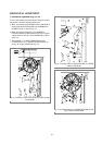
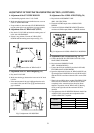
K.Adjustment of the AUDIO AZIMUTH
a. Connect the AUDIO output JACK with an AUDIO
LEVEL METER.
b. Play back the ALIGNMENT TAPE(DN-2:MONO-
SCOPE 7KHz Signal).
c. Check if the AUDIO output signal level is over : -9 ~-
3dBm.
d. If the requirement of “c” is not satisfied, readjust the
AZIMUTH SCREW of the AC HEAD until the AUDIO
output is maxized.(Fig. 5.4)
e. Repeat the Process of “Adjustment of the wave form of
DRUM Entrance/Exit”
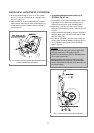
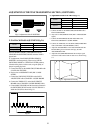
L. X-POSITION
a. Connect the PT01 on the MAIN CIRCUIT BOARD with
a PATH ADJ.FIXTURE.
b. Play back an ALIGNMENT TAPE(DN-2: MONO-
SCOPE Signal).
c. Connect theS/W PULSE TEST PIN on the PATH
ADJ.FIXTURE with a CHANNEL-1 SCOPE PROBE.
d. Connect the VIDEO OUT on the MAIN CIRCUIT
BOARD with a CHANNEL-2 SCOPE PROBE(1V/div)
e. Check if the ENVELOPE is maximum when the VR
CONTROL on the PATH ADJ. FIXTURE is in CEN-
TER.
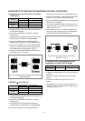
f. If the requirement “e” is not satisfied, readjust the X-
POSITION by referring to subitem “E”(Adjustment of the
X-POSITION).
g. Repeat the process of subite, “F(PLAYBACK PHASE
ADJUSTMENT).
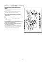
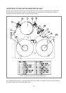
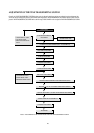
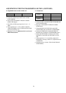
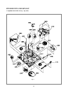
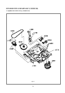
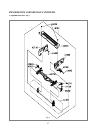
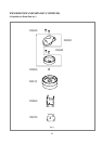
ADJUSTMENT OF THE TPAE TRANSPORTING SECTION. (CONTINUED)
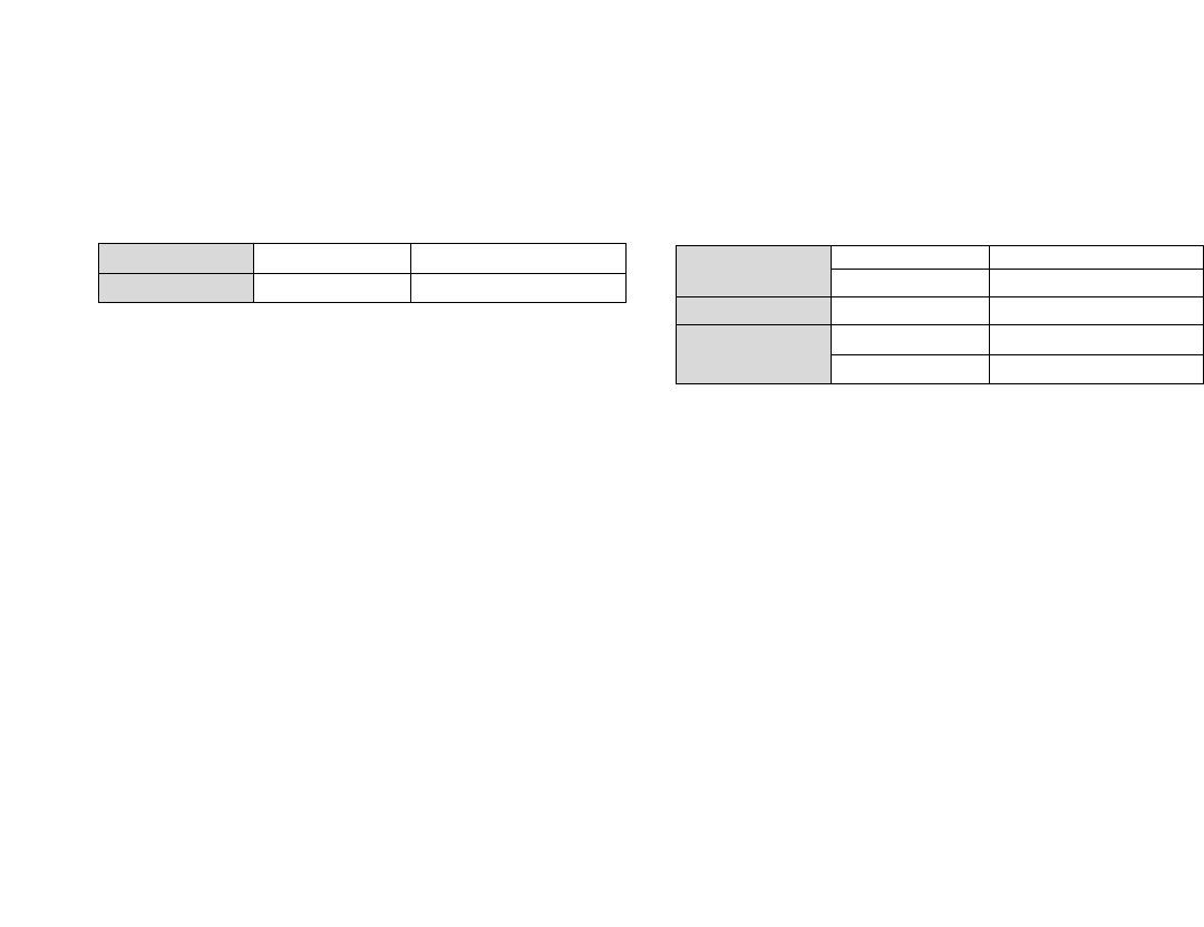
AUDIO OUTPUT AUDIO OUTPUT JACK
AUDIO LEVEL METER
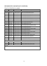
Test Point
Measurement Equipment
S/W PULSE TEST PIN PATH ADJ. FIXTURE
ENVELOPE TEST PIN PATH ADJ.FIXTURE
Measurement Equipment OSILLOSCOPE
VR CONTROL PATH ADJ.FIXTURE
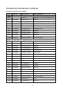
S/T GHIDE ROLLER TAPE TRANSMISSON SECTION
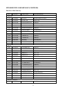
Test Point
Adjustment