


9
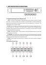
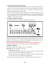
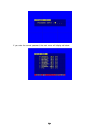
3.1 Back panel and connection terminals
The power cable and input, output signal terminals are all at the back of the machine, the
connection to monitor, camera etc equipments are all carried out through the terminals and
sockets on the back panel the back view of the machine is illustrated as below.
Each part of the back panel is illustrated as below:
1. Video input CH1-CH16 2.main output 3.assistant monitor 4.S-VIDEO 5.audio input 6.audio
output 7.net interface 8.USB port 9.power 10.debug port 11.Alarm and RS485 ,port define:
(1-12: sensor1-sensor12; 13, 20, 24, 25: GND, 14-17: sensor 13-sensor16, 18: RS485A 19:
RS485B, 21: COM 22: NC 23: NO)
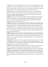
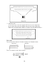
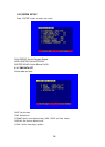
3.2 Video and Audio Connection
The DVR can support up to 16 cameras video input at the same time.
AUDIO
IN
OUT
3 4
21
S VIDEOOUT
OUT
CH16
CH8
CH15
CH7
CH14
CH6
CH13
CH5
CH12
CH4
CH11
CH3
CH10
CH2
CH9
CH1
Main
Out
Assisant
Out
S Video
Out
VideoIn1
Video In 16
Microphone
The DVR can connect 4 channel’s audio input, but you can only select one for recording. To
display the DVR picture, the DVR video output signal should be transferred to your TV set or
monitor. Any TV set that has a “video input” terminal is suitable for displaying the image. The
figure above shows the video and audio signal line connection.
Notice: you can only connect one audio input at any one time, which means, if you
connect an audio input to CH1, you cannot connect any to CH2 through CH4.
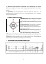
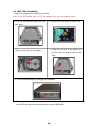
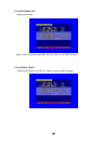
3.3 Alarm Connection
The DVR can support up to 16-alarm input and 1 alarm output.
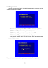
Alarm input: there are two types of alarm input.
1. Voltage output (5V and 0V)
A: In case sensor output high voltage (5V) normally and output low voltage when trigg
ered (0V), then users must set DVR as low voltage alarm.
B: In case sensor output low voltage (0V) normally and output high voltage when trigg
ered (5V), then users must set DVR as high voltage alarm.
Please refer to the picture below, channel 2 to channel 16 are the same as channel 1.